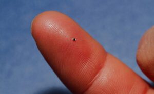
Electronic components come in all shapes and sizes, ranging from extremely complex land/ball grid array components to simple axial resistors and capacitors. If you have experience working with SMD components, you’re probably familiar with chip resistors and their wide range of package sizes. Among the smallest, and yet most popular, is the 0402 resistor, and its very small footprint with SMD pads.

Thin film resistor in 0402 package
Although these components have a rather small power rating, they have plenty of uses in a range of devices, basically including any modern digital system. A 0402 package footprint needs to be carefully designed in your CAD tools to complete your PCB layout successfully. Here’s what to watch for in a 0402 package footprint and where you can find verified footprints for all your components.
0402 Package Footprint Dimensions
The 0402 package is nearly the smallest chip resistor package; only the 0201 chip resistor package is smaller. The small size of 0402 resistors puts their power dissipation rating quite low compared to larger resistors or comparable axial resistors. This then limits the current you can run through these devices. This table below shows some of the standard chip resistor component dimensions with associated power ratings; though, it’s important to note resistors vary in size between manufacturers.
SMD chip resistor sizes and codes
These packages are highly standardized, making it quite easy to build a 3D CAD model for one of these components. In fact, your PCB design software likely comes packaged with libraries for popular SMD components, including 0402 resistors; these libraries will include a simple schematic symbol, PCB footprint with IPC-compliant land pattern, and 3D CAD model. Generic component models (i.e., non-specific to any manufacturer) will normally use the basic passive circuit symbol for the schematic symbol and they may not have a specific PCB footprint or 3D model.
Creating Your Own 0402 Package Footprints
One thing should be obvious from the above table: 0402 package resistors are extremely small! Although a 0402 chip resistor is quite small, the land pattern and component courtyard outline you need might be rather large, depending on the assembly procedure used to finish your boards. In fact, due to difficulties in assembly and soldering, 0402 land patterns seem to be notoriously difficult to design. In short, there is no universally accepted land pattern for small resistors, such as the 0402 and 0201 packages.
You’ll need to custom-design PCB footprints for these chip resistors and you’ll need to refer to your manufacturer’s specifications when working with 0402 land patterns. The package outline has fixed dimensions, but land patterns need to be designed to accommodate the assembly and soldering processes.
If the land pattern is not designed correctly, the component is at danger of tombstoning during assembly. In effect, an incorrectly-sized footprint can lead to insufficient heating at one end of the component during soldering. As the solder cools and solidifies, it can pull the other end of the component off its solder pad.
Tombstoned SMD resistor
There are other causes of tombstoning, including lack of thermal reliefs. Note in the above image, everything is surface-mounted; the copper connected to the lands is quite heavy and pulls heat away from the pad, just as what occurs in pads connected to a large plane. Land patterns for larger wave-soldered chip resistors tend to be larger than the pad sizes required for reflow soldering. 0402 and 0201 chip resistors are generally not used in wave soldering processes. Components for use in hand-soldered boards tend to be even larger simply to provide access to the edge of the component with a soldering iron.
Whether you’re working with 0402 package footprints or some other common ICs, you can find mechanical models for your components in your datasheets or on the manufacturer’s website. If you want to prevent assembly defects, you can consult your manufacturer to find their recommendation on land pattern sizes for 0402 and 0201 chip resistors.
Passive manufacturers also release land pattern design recommendations for components in wave or reflow soldering processes. Take a look at this datasheet from Vishay for a great example; note they also provide wave and reflow soldering profile data.
Finding Verified 0402 Package Footprint Files
Be careful when pulling footprints for 0402 and other chip resistors from forums, GitHub libraries, and even from part creation services. These land patterns might be mislabeled or they might be incorrectly designed altogether. 0402 footprints from different manufacturers are not created equal. Your best bet for ensuring reliability is to use footprints designed to the IPC-SM-782 Surface Mount Design and Land Pattern Standard
If your PCB design software does not contain the footprints you need for common components, you’ll need to choose one of the following courses of action:
- Create your own PCB footprints: Be sure to keep the points above in mind if you go this route. Take a look at the IPC-SM-782 standard as well.
- Browse distributor websites: This is fine if you know you can source the resistors you need, but not all distributors provide these component footprints.
- Use a component search engine: The best search engines compile data from multiple distributors, manufacturers, and even other component data aggregators. The data you can access includes CAD models, sourcing data, technical specifications, and datasheets.
When you’re looking for 0402 package footprint files and 3D models in vendor-specific ad vendor-neutral formats, you can find the components you need with the parts search features in Ultra Librarian. You’ll have access to verified CAD models that can be imported into popular ECAD applications and you can view sourcing information from worldwide distributors.
If you’re looking for CAD models for common components, Ultra Librarian helps by compiling all your sourcing and CAD information in one place. Working with Ultra Librarian sets up your team for success to ensure any design is going through production and validation with accurate models and footprints to work from. Register today for free!