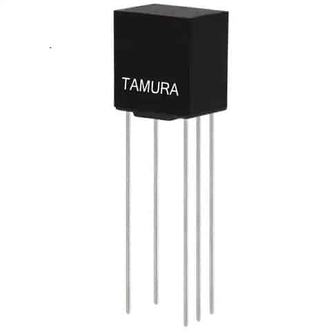
3D view of the MET-24 Signal Audio Transformer
The proliferation of digital electronic technology has transformed virtually every aspect of our lives over the last few decades. This explosion owes much to the utilization of active components including diodes, transistors, and amplifiers. Nevertheless, there is still a great need for passive components such as resistors, inductors, and capacitors. An often unsung hero of the passives is the transformer, a component that performs critical functions.
For many, including electrical engineers, the term transformer brings to mind a large metal can attached to power poles or a large, fenced-in element commonly found at feeder or distribution stations. It is true that transformers are essential elements of power transmission and distribution (T&D); however, smaller versions are also common in electronic systems and on PCBAs. An excellent example is the MET series of audio transformers.
In this article, we take an in-depth look at the MET-24 datasheet, which provides important specifications and design information to aid you in making the best utilization of this component’s functionality for your board design and development.
The MET-24 Audio Transformer
Transformers in electronic circuits and systems perform basically the same functions as their larger cousins do for high voltage power systems. Transformers can step-up or step-down voltages and currents between circuits, isolate or limit the effects of one circuit on another, maximize power transfer from one circuit to another, or supply multiple loads from a single source. Transformers used on circuit boards are typically classified as RF or signal transformers. If the input signal range is limited to or includes the human audio band—approximately 20 Hz to 20 kHz—the component may be referred to as an audio or signal audio transformer, as is the MET-24.
Specifications and Parameters
The MET-24 from Tamura Corporation can be classified as a signal audio transformer, as its rated frequency response (shown in the electrical specifications below) indicates the passing without attenuation of signals that include the audio band.
MET-24 operating specifications
The parameters and specifications shown above (from the MET-24 datasheet) are relatively fixed; therefore, the MET-24 is limited in its application. However, this transformer model is but one of a series, which provides a range of alternatives to meet your particular design needs.
Alternatives to the MET-24
Alternative audio transformers to the MET-24
As shown in the table above, the basic model—which includes the MET-24—extends to include various signal audio transformer components. These variations include a turns ratio range from 1:1 to 22.3:1, primary impedance from 135 Ω to 200 kΩ, secondary impedance from 3.2 Ω to 10 kΩ, and DC blocking current levels from 10 mA to 0 mA. With this number of options, the MET-XX series is a good source to explore for meeting your signal audio transformer circuit functionality needs.
Let’s take a look at how to use the MET-24 datasheet.
How to Best Use the MET-24 Datasheet
One of an engineer and/or PCBA designer’s most valuable assets when designing circuit boards is the ability to effectively read a component datasheet. Although exact content and detail may vary for different types of parts, most datasheets will contain specific guidelines, information, or dimensions to aid you in creating schematic symbols and footprints and building the BOM for your design.
Creating Schematic Symbols and Footprints
When generating the schematic for your design, it is helpful to have a symbol diagram that makes it easy for other designers and technicians to understand your circuit’s operation. Even more critical is the pinout, as it ensures signals are routed accurately on your manufactured board. As shown below, the MET-24 datasheet includes these important attributes.
PCB design data from the MET-24 datasheet
In addition to schematic capture information, the MET-24 datasheet includes detailed drawings and dimensions for creating your PCB footprint.
Support for BOM Generation
Whether you create your footprint from scratch or elect to avoid the pitfalls of manual footprint creation, you will need to compile an accurate BOM for your contract manufacturer (CM) to build your board. The datasheet is also very helpful here, as it provides capabilities and specifications that aid in your component selection. The most efficient and convenient way to create a BOM is to centralize your component gathering, which can be efficiently done using a Part Request, as shown in the figure below.
MET-24 component request using Ultra Librarian
The request tool above is one of the many services offered by the world’s largest PCB CAD library, Ultra Librarian (UL). Not only does the UL library contain CAD files and datasheets for millions of parts, you can also source components for your BOM from over 2500 manufacturers worldwide and all of the major distributors from one location.
If you are looking for CAD models from reliable, seasoned components that are not readily obtainable—such as from the MET-24 datasheet—or to centrally assemble your BOM to streamline procurement for you or your CM partner, Ultra Librarian helps by compiling all your sourcing and CAD information in one place. Working with Ultra Librarian sets up your team for success to ensure any design is going through production and validation with accurate models and footprints to work from. Register today for free.