The QFN package for the CP2102 and CP2104 USB-to-UART bridge controllers. Image from Silicon Laboratories
Electronic components that enable interconnection and/or communication between different circuit boards and electronic systems are often referred to as bridges. These devices are essential for telecommunications and other operations, as it is common that connected or networked systems that employ various internal protocols must be able to talk to each other. Additionally, bridge circuits are utilized for evaluation and reference designs to enable the board to connect to various types of peripherals.
USB-to-UART bridge controllers are specialized devices that fall within this group of bridge components. In this article, we compare two bridge controllers manufactured by Silicon Laboratories—the CP2102 vs. CP2104—to understand their similarities and differences and help you determine which one to implement in your design.
The CP2102 Bridge Controller
Today, there is a virtually universal thrust toward smarter operations and systems. To achieve the goal of integrating various advanced technologies, effective communication between electronics products, devices, and circuit boards is required. The challenge is that different electronic systems utilize different signal types for internal processing. Therefore, bridge circuits or modules are used for conversion and to enable signal transmission and reception between these devices. One such bridge component is Silicon Labs’ CP2102.
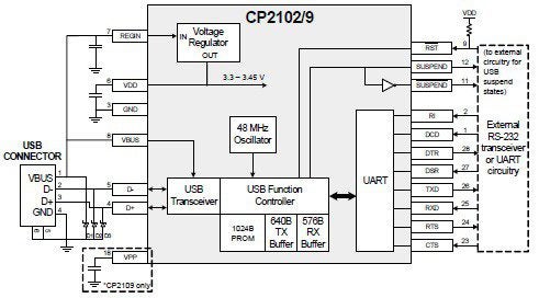
The CP2102, shown in Fig. 1 below, is a highly integrated USB-to-UART bridge controller that provides an easy means of connecting devices with the older RS-232 protocol to USB.

Fig. 1 CP2102 block diagram
As the block diagram from the CP2102 datasheet illustrates, a UART interface is utilized to enable the conversion to USB, and the device also includes an internal voltage regulator to stabilize operation.
Device Specifications

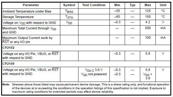
Fig. 2 Maximum electrical parameters
In Fig. 2 above, important restrictions on the controller’s operation are listed. In addition to these constraints, the UART interface is limited to a baud rate of 921,600 bps and an input voltage range of 2.0 V to 0.8 V, the voltage regulator accepts an input voltage from 4.0 V to 5.2 V and produces an output voltage of 3.0 V – 3.6 V (typically 3.3 V), and the USB transceiver outputs a voltage between 2.8 V and 0.8 V with a crossover range of 2.0 V – 1.3 V.
CP2102 Uses and Capabilities
The CP2102 is intended for use with data communications equipment (DCE) and data terminal equipment (DTE). Common examples of these systems are listed below.
DCE Devices
- Modem
- Hub
- ISDN adapter
DTE Devices
- Computer
- Printer
- Scanner
- Network interface card (NIC)
The bridge controller simulates the port of the system to which you are connecting, enabling devices that use the RS-232 protocol to be utilized by a device that employs USB communications. To achieve this, the CP2102 has the following functionality and capabilities:
CP2102 Features
- Integrated USB transceiver
- Voltage regulator on chip
- Integrated clock on chip
- Erasable EPROM for device information editing and storage
- USBExpress™ direct driver support
- Royalty-free license
- Plug and play operation with Windows, Apple, and Linux operating system devices
The CP2104 Bridge Controller
Another integrated USB-to-UART bridge controller from Silicon Labs is the CP2104. A block diagram of this controller from the CP2104 datasheet is shown in Fig. 3.
Fig. 3 CP2104 system diagram
Similar to the CP2102, the operation of the CP2104 controller is bounded, as shown in the figure below.
Fig. 4 CP2104 maximum electrical parameters
Comparing figures 1 and 2 with 3 and 4, it is obvious that the CP2102 and CP2104 share these major elements: a USB transceiver, UART interface, and voltage regulator. However, as is indicated by the corresponding datasheets for these components, there are differences that should influence your decision as to which device best serves the needs of your design.
The CP2102 vs. CP2104: Which Should I Use in My Design?
In order to choose between the CP2102 vs. CP2104, it is necessary to delve deeper into the capabilities and functionality of these devices to discover their significant differences and similarities.
The Differences and Similarities Between the CP2102 and CP2104
In Fig. 5 and 6, the pin assignments and descriptions are shown for the CP2102 and CP2104, respectively.
Fig. 5 Pinout of the CP2102
Fig. 6 CP2104 pinout
These show that both controllers have similar functionality, as many of the same connection requirements are indicated for each device. However, an inspection of the CAD files for each component—Fig. 7 for the CP2102 and Fig. 8 for the CP2104—reveals that different schematic, footprint, and 3D models are required to accurately incorporate these devices in your design.
Fig. 7 CAD images for the CP2102
Fig. 8 CAD images for the CP2104
These and other significant differences are listed in the table below.
| The CP2102 vs. CP2104 | ||
| Attributes | CP2102 | CP2104 |
| Package | 28-pin QFN
(5 mm x 5 mm x 0.9 mm) |
24-pin QFN
(4 mm x 4 mm x 0.75 mm) |
| EPROM programming | Erasable | Non-erasable |
| UART baud rate | 300 – 1M bps | 300 – 2M bps |
| RS-485 mode | No | Yes |
| Windows OS virtual com port drivers | 8®7®/Vista®/XP®/Server 2003®/2000® | 7®/Vista®/XP®/Server 2003®/2000® |
| Mac OS virtual com port drivers | OS-X/OS-9 | OS-X |
As the listings above indicate, the CP2102 and CP2104 are comparable components in terms of most applications. However, care must be taken when selecting your controller to ensure that not only are you satisfying your performance goals, but also that your data is accurate for a first pass yield design to facilitate right-first-time (RFT) manufacturing by your CM.
If you’re looking for CAD models for common components or to compare similar parts, such as the CP2102 vs. CP2104 USB-to-UART bridge controllers by Silicon Laboratories, Ultra Librarian helps by compiling all your sourcing and CAD information in one place.
Working with Ultra Librarian sets up your team for success to ensure streamlined and error-free design, production, and sourcing. Register today for free.