 Although the electronics industry loves to talk about making things smaller and faster, not all power systems are integrated onto a board with a small footprint. Some power systems must provide highly regulated power over long distances with resistive cables, creating an opportunity for losses as power is transferred to the system load. In the worst-case scenario, the power supply goes out of regulation simply because the cable’s resistance was too large.
The simple method to overcome the loss of regulation related to power loss is to track the output, but how can this be done over long cable runs? While bulkier cabling could be used, this will not prevent loss of regulation or help maintain ripple within strict levels. Instead, a component like the LT4180 is one solution that allows regulation to be maintained over long cable runs without requiring a change in the cable length, wire thickness, or connector style.
LT4180 Operation Principle
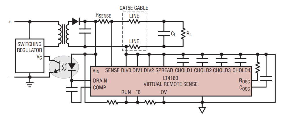
The LT4180 operates as part of a feedback loop in a power converter, with the typical application being in an isolated DC-DC switching converter. The role of the LT4180 is to perform a similar function as a current sense amplifier, where the output voltage being delivered to the system load is monitored with a current-sense resistor. In addition to monitoring current output, the design compensates for potential power loss and maintains regulation by continuously interrogating the impedance of the cable run that is used to deliver power to the load component. The LT4180 can actively monitor and adjust the output power to maintain regulation within a tight margin.
A typical application circuit from the LT4180 datasheet is shown below. In this example, the output current from an isolated DC-DC switching converter is passed over a sense resistor to determine the output voltage. Power is delivered over a standard CAT5E cable, and the voltage readout over the cable input is used to determine the required adjustment to the output power. This scheme, where the cable impedance is interrogated while the power system operates, eliminates the need for two additional sense wires running along the power delivery cable, which may themselves be subject to DC losses and inaccurate power delivery measurements.

LT4180 application circuit for a typical isolated DC-DC converter. [Source: LT4180 datasheet]
Note the use of a transformer in this converter (either flyback or LLC resonant converter would be applicable here). It is important to note that the LT4180 does not directly adjust power output or regulation over the output voltage from the switching converter stage. Instead, it is used to modulate the current in the LED of an optoisolator.
Using an optoisolator allows a switching regulator controller or gate driver on the primary side of the transformer shown above. Although the switching regulator section is shown as a single block, it could be broken into a set of discrete gate drivers and MOSFETs, including in a bridge configuration that would be used in high current applications.
If a system operates without galvanic isolation (meaning a typical buck/boost/buck-boost converter without a transformer), it won’t need the optoisolator section. This means the open-drain output could be connected to a resistor and the level readout in parallel on the sense pin of a switching regulator controller or configurable gate driver. As long as the controller chip or circuitry has a feedback sense/input pin, it can be used with the LT4180, either in an isolated or non-isolated power supply.
Specifications and Applications
The table below shows the basic specifications, packaging data, and basic features in the LT4180.
| Input voltage range | 3 to 50 V |
| Sense voltage range | 300 mV (not to exceed input voltage) |
| Input pin current | 10 mA |
| Maximum junction temperature | 125 °C |
| Open-drain feedback current | Limited to 12 mA maximum (typical value) |
| Overvoltage/current protection | Integrated in-package |
| Transient control | Slow turn-on with internal damping |
| Package | 24-pin SSOP package |
The output open-drain current limit used for feedback and control is somewhat low but still enough to drive a typical optoisolator directly. Be sure to compare this value with the forward current in your optoisolator datasheet if the LT4180 will be used in an isolated power supply design.
Finally, note that the allowed input voltage spans a broad range. This is sufficient to cover automotive applications operating at 48 V DC, industrial power applications at 28 V DC, and typical logic levels. If your isolated power supply design will be used to supply power over long cables in any of these areas, consider using this component to ensure accurate load regulation and power delivery.
When you need to find PCB, sourcing information, or datasheets for the LT4180, use the complete set of search features in Ultra Librarian. The Ultra Librarian platform gives you access to PCB footprints, technical data, and ECAD/MCAD models alongside sourcing information to help you stay ahead of supply chain volatility. All ECAD data you’ll find on Ultra Librarian is compatible with popular ECAD applications and is verified by component manufacturers to help streamline your operations.
Working with Ultra Librarian sets up your team for success to ensure streamlined and error-free design, production, and sourcing. Register today for free.


