High energy particles such as photons, protons, and neutrons negatively impact electronics components – either in the form of charge build-up or particle dislocation. The effects are similar to hitting the PCBA with a golf ball but at the atomic level. Thus, the effect is much more mechanical than chemical. Therefore, it is imperative to understand the possible radiation effects on electronics devices and ideal early design considerations to avoid them in the first place.
Particle Radiation Types
Radiation can be electromagnetic or subatomic. Different radiations fall into these categories as follows.
Electromagnetic
- X-rays
- Gamma rays
Subatomic particles
- Protons
- Neutrons
- Electrons
- Pions
- Muons
It is imperative to know that not all radiation effects on electronic devices are equal. Here is the list of different types of radiations with their characteristics for your reference.
| Characteristics | Alpha () | Proton (p) | Beta ()or Electron (e) | Photon ( or X ray) | Neutron (n) |
| Charge | +2 | +1 | -1 | neutral | neutral |
| Ionization | Direct | Direct | Direct | Indirect | Indirect |
| Mass (amu) | 4.001506 | 1.007276 | 0.00054858 | – | 1.008665 |
| Velocity (cm/sec) | 6.944108 | 1.38109 | 2.821010 | 2.9981010 | 1.38109 |
| Speed of Light | 2.3% | 4.6% | 94.1% | 100% | 4.6% |
| Range in Air | 0.56 cm | 1.81 cm | 319 cm | 82,000 cm* | 39,250 cm* |
Alphas have the shortest penetration depth among rest particles. Alpha particles are easily stopped inside the material of components. Betas have a relatively more extended penetration depth than Alphas but can’t move through the material. On the other hand, Gammas and X-rays are pure energy with no mass. Thus, they can easily penetrate through the component, which is the most valuable property for imaging devices.
Factors Affecting the Radiation
Sources of Exposure
PCB components can be exposed to different degrees of radiation based on the background as in:
- Terrestrial background: radiation coming from the geographical area
- Cosmic background: radiation from the universe varying with altitude level
Apart from these natural exposures, components can also get artificially exposed to radiation at airports, post offices, or delivery companies for inspection or quality assurance purposes.
Radiation Type
High energy particles and large particles, such as photons, can significantly damage the components. Gamma and X-rays have no mass. They will need a huge amount of energy to cause any damage.
Energy
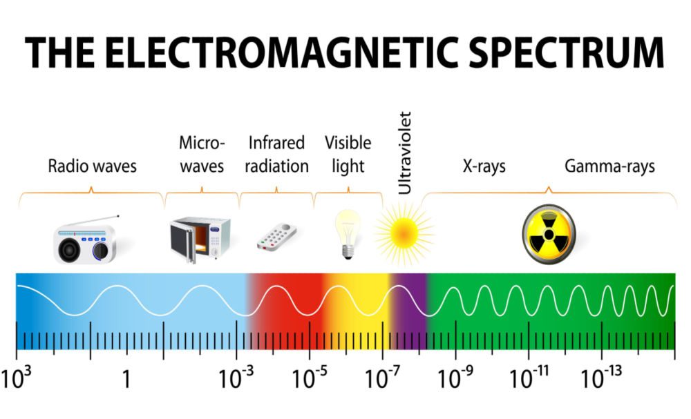
There are two types of radiation- ionizing and non-ionizing. Non-ionizing radiations, such as radio waves and microwaves, have low to moderate energy to set molecules on vibration. However, ionizing radiations- such as alpha, beta, and gamma particles-have enough energy to displace electrons from the material.
Radiation Flux
If the amount of particle radiation received per unit time, also known as radiation flux, is high, the components will get damaged as soon as the radiation nears its minimum energy threshold. At this point, it can successfully remove electrons from the material.
Various Particles Radiation Effects on Electronics Devices
Dose Effects
There are different exposure dependencies. The first one is time-dependent or dose effect. As the time of exposure increases, the dosing effect increases. A large amount of dose accumulation by the PCB material can lead to two types of effects.
Total Incidence Dose (TID)
This represents the total amount of radiation absorbed by the PCBA material in its lifetime. High accumulation of charges at the silicon surface can lead to a change in threshold voltage, generation of leakage current, or rise in response time. Prolonged exposure can cause a device to become non-functional.
There are two types of units to measure radiation effects on electronics devices; Rads (Si) and Gy. Rads stand for radiation absorbed dose.
The table below shows an approximate random total dose damage threshold for various types of semiconductor devices.
| Type of Semiconductor Device (COTS) | Total Dose Threshold
Rads (Si) |
Total Dose Threshold
Gy (Si) |
| Linear | 2,000 – 50,000 | 20 – 500 |
| Mixed signal | 2,000 – 30,000 | 20 – 300 |
| Flash memory | 5,000 – 15,000 | 50 – 150 |
| Dram | 15,000 – 50,000 | 150 – 500 |
| Microprocessor | 15,000 – 70,000 | 150 – 700 |
Displacement Damage Dose (DDD)
This happens when a proton strikes a silicon atom and knocks it off the lattice. The effect causes traps in the silicon, which can tie up with electrons and holes to increase leakage current. The possibility of the DDD effect for an electronic device depends on its silicon feature size, active junction depths, and process technology.
Single Event Effects (SEE)
When the PCB component is randomly exposed to random heavy ions, they blast through the material and cause destructive or non-destructive effects. This is known as Single Event Effects (SEE). The particles may cause temporary issues such as noise and a bit-flip in memory or can lead to permanent failure in terms of device latch-up and failure of the transistor gate dielectric.
How to Minimize Radiation Effects on Electronic Devices?
Depending on the type of radiation (ionizing/non-ionizing), there are certain design guidelines you can follow to minimize radiation effects on electronics devices.
For Non-ionizing Radiation
Best Route Tracing
Avoid tracing two signal layers adjacent to each other as much as possible. Instead, add a ground plane in between or route them orthogonal to each other to avoid signal interference.
Good Impedance Control
Applying the best impedance control is imperative to retain signal integrity. It will ensure that your signal arrives with the minimum distortion possible. Here, the most important task is to choose substrate material to have a uniform impedance of a trace over its entire area. With the desired impedance level in mind, your CM can choose the right substrate materials that come within tolerance.
Electromagnetic Shielding
Adding electromagnetic (EM) shielding to components protects them from particle radiation and EMI. As the shields are connected to the ground, any leakage current is produced as the effect gets grounded without interfering with sensitive signals. You may shield boards, components as well as cables to increase their reliability and retain signal integrity.
For Ionizing Radiation
Use Rad Hard Rated Components
Radiation-hardened electronics components have been specifically designed to withstand damage caused by ionizing and high-energy radiations. They are made up of specific materials such as silicon carbide, gallium nitride, hydrogenated amorphous silicon, etc. Rad Hard rated components can withstand certain amounts of TID and overcome the SEE effect to a certain extent.
It is also imperative to choose the right kind of component for a high radiation environment, as shown below.
| Component | High radiation | Not recommended |
| Connectors | Unaffected | – |
| Resistors | Unaffected | – |
| Capacitors | Polymer, Ceramic | PTFE, Tantalum,
Electrolytics |
| Semiconductors | Rad-Hard, Silicon on
Insulator (SOI), Silicon on Sapphire (SOS), Power PMOS |
Unhardened MOSFETs,
CMOS with Parasitic SCR, Power NMOS |
| Oscillators | Swept Quartz | Unswept |
While looking for ideal components to design radiation-proof PCB, let Ultra Librarian help you compile all sourcing and CAD information at one place. Working with Ultra Librarian sets up your team for success to ensure streamlined and error-free design, production, and sourcing. Register today for free.


