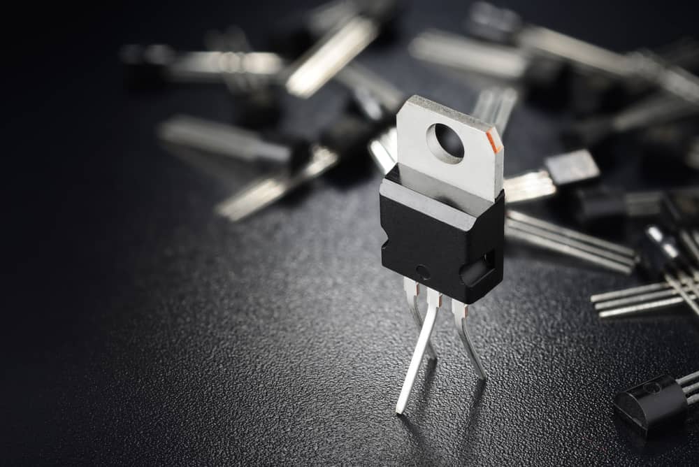
Usually, BJT transistors are used for small current applications, whereas MOSFETs are reliable for high current applications. The MOSFET has two types: enhancement type and depletion type. The depletion type acts as a normally closed switch, whereas the enhancement type acts as a variable resistor controlled by voltage.
It further comes in N-channel and P-channel types. The former type is, by far, the most common transistor used today. The 2N7000 is an N-channel enhancement MOSFET. Before we look at 2N7000 circuit applications, let’s learn some of the essentials for this component.
Understanding Basic Operation of 2N7000 MOSFET
It’s an N-channel enhancement MOSFET (metal oxide field effect transistor). As the name suggests, a field effect transistor works by voltage. When voltage is applied between the drain and source, current flows from the drain to source. Depending on the voltage applied between the gate and source (VGS), the resistance between the drain and source (RDS(ON)) will vary. If the voltage is low, the resistance is high and vice versa. In short, MOSFETs are variable resistors controlled by voltage.
Thus, initially, when V GS =0, the MOSFET acts as an open switch. But as we increase the VGS, the output resistance starts to drop very quickly. The output current is the multiplier of the input.
If we take a look at the ON characteristics of the 2N7000 MOSFET, we get the following information.

As we can see, RDS(ON) is given for different voltage sources. The 2N7000 offers lowest resistance path when the gate to source voltage is 10 V, and offers a typical 2 resistance at the minimum threshold voltage of 4.5 V.
As this is a power MOSFET, the resistance value is high in order to handle large loads. In case of logic level MOSFETs, this value typically stays in milliohms.
Design Considerations
Pin Layout
With the flat part facing up, you will find the source to the left, the gate to the middle and the drain to the right.
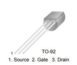
Make sure to connect Source and Gate to the negative terminal and positive terminal of the battery respectively. The load is connected to the drain. Current flows from drain to source and electrons flow in the opposite direction.
Maximum Limits
Make sure to operate the device within its absolute maximum limit. Otherwise, the device may fail due to overheating or may get permanently damaged.

The table above shows the absolute maximum ratings for 2N7000 (TO-92 package) and 2N7002 (SOT23-3L), respectively.
Under no condition, the gate to source voltage should be more than 18 V and the no-input drain to source voltage should be more than 60V.
Maximum Power Dissipation
It’s also imperative to know the maximum heat the transistor can dissipate without any heat sink.

For example, let’s say we are running a 100 mA load with the 2N7000 transistor.
Power dissipation (P) required:
= Current (I) RDS2
= 0.1 22
= 0.4 mW
Let’s calculate the dissipation capacity of 2N7000 MOSFET.
From the datasheet we have:
Junction to ambient temperature (Rthj-amb) = 125 °C/W
Max junction temperature = 150 °C
The maximum power the transistor can dissipate can be calculated as follows
= (max junction temp – ambient temperature)/ Junction to ambient temperature
= 150-25/125= 1 watt
As the power dissipation on load is less than the maximum power dissipation capacity of the MOSFET, it is safe to use.
Some Popular 2N7000 Circuit Applications
The 2N7000 MOSFET can be useful in the following applications:
Switch
You can operate 2N7000 as a switch by operating it either in saturation mode or cut-off mode. Once the VGS crosses the threshold voltage, the MOSFET will turn On. On the flip side, when the gate-source voltage is zero, the device will be turned off, and the output will read VDD. (DC voltage supplied to the drain of the transistor).
One of the 2N7000 circuit applications is to switch the power supply in a basic buck converter, as shown below.
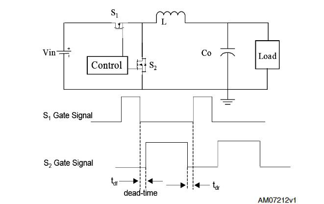
As shown in the figure above, a basic DC-DC power supplier has two N-channel MOSFETs. One will store the energy from the inductor, while the other will release it into the load during alternative cycles of the AC supply.
Motor Control
A motor control uses two types of control circuits: half bridge and full bridge. The former will have two MOSFETs, while the latter will have four MOSFETs to control the operation. If we are talking about controlling the speed of brushless stepper motors, use of power MOSFET in a pulse width modulation control circuit.
Solid State Relays
Two 2N7000 transistors can be utilized to design an Optical Solid State Relay (SSR). This is used to switch electrical loads using an LED’s infrared light as input energy.
It consists of an infrared LED, PVD (photovoltaic diode), and MOSFETs.
The light emitted from the LED is detected by the PVD. The PVD converts it into an equivalent voltage which is then applied to the gate of the MOSFET to switch the drain current ON and OFF. Here two MOSFETs are connected serially in reverse to work for both cycles of an AC supply.
Amplifier
The N-channel enhancement MOSFET is a typically OFF transistor, but you can turn it on with a proper gate to source voltage. It is a voltage-controlled device. As the bias voltage increases, the output voltage also increases. Thus, you can use the 2N7000 MOSFET as amplifiers for radio-frequency applications in sound systems.
Ultra Librarian features a huge online library for fetching additional resources, such as datasheet, secondary components, CAD/ECAD models, etc. for designing 2N7000 circuit applications with ease. Even access real-time component availability status along with their price- all in one place. Working with Ultra Librarian sets up your team for success to ensure streamlined and error-free design, production, and sourcing. Register today for free.


