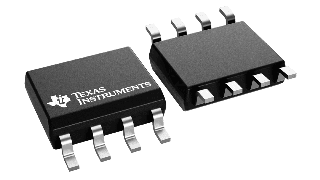
LM155 timer circuit
Next to signal integrity, which includes EMI and EMC, the most crucial consideration when designing electronic circuit boards is timing. Without stable and accurate duty cycles and triggering, erroneous signals, misread data streams, and even no output are possible. Therefore, it is critical to ensure your timing control source(s) are reliable.
Texas Instruments, an industry leader in building advanced semiconductor devices like GaN technology switches to maximize power efficiency, also makes high-quality ICs to stabilize your design’s timing. One such component is the LM155. And by combining the information provided in the LM155 timer circuit datasheet with verified symbol, footprint, and 3D model data, you can optimize your designs that implement this reliable timing device.
Features and Applications of the LM155
Many timing devices, like crystals, are typically implemented as set frequency oscillators. The LM155, however, is a feature-rich integrated circuit (IC) with many possible applications, as listed below.
Features of the LM155 timer circuit
|
Common Applications for the LMi55 Timer
- ➡ Linear Ramp Generation
- ➡ Precision Timing
- ➡ Pulse Generation
- ➡ Pulse Position Modulation (PPM)
- ➡ Pulse Width Modulation (PWM)
- ➡ Sequential Timing
- ➡ Time Delay Generation
LM155 Timer Circuit Datasheet Data and Information
As detailed in the LM555 timer circuit datasheet, the device is most commonly applied for time delay or oscillation. Additionally, the circuit can be triggered and reset externally. In the figure below, the general block diagram is shown.
LM155 block diagram
As shown above, the LM155 has four major internal circuits or stages: two comparators, a flip-flop and an output. These are expanded upon in the following schematic diagram.
LM155 schematic
As the diagram above illustrates, the operation of the LM155 is straightforward and dependent on external controls for threshold setting, triggering, and reset.
Important Characteristics
As discussed above, The LM155 timer circuit is a reliable timing device. It is also flexible and can be used for many different applications; the provided operation is maintained within the constraints in the table below
Absolute maximum specifications for the LM155 timer circuit
Additionally, the electrical characteristics below must be used as guidelines for your design.
LM155 electrical characteristics
Pin Descriptions
The LM155 comes in one of three 8-pin package types. Each has the pinout shown below.
LM155 pinout and pin descriptions
As described above, the LM155 timer circuit has two outputs. One is the timing signal or waveform (pin 3). The other is the ground reference (pin 1), which is critical for proper synchronization. Inputs include a threshold and trigger level control voltage(pin 5), the threshold (pin 6) and trigger (pin 2), a discharge port (pin 7), supply voltage (pin 8), and reset (pin 4). The LM155 timer circuit datasheet is comprehensive and includes performance characteristics and example configurations for a design that can help create the best circuit design.
Optimizing Design with the LM555 Timer
Choosing the LM155 as a primary timing device for your PCBA will add stability and reliability to your design. First, however, it is essential that you leverage the design information included in the LM155 timer circuit datasheet.
An excellent reference from the datasheet that can simplify the schematic capture for your design and likely save you time is to implement either the astable or monostable typical circuit configuration, as shown below, for the operation mode required for your application.
Typical LM155 astable circuit
LM155 monostable configuration
For both monostable, the most common, and astable operation modes, your choice of capacitors and resistors is essential. The datasheet provides guidance and equations for determining the values for these parts. However, for your PCBA layout, it is imperative that when utilized accurately and verified schematic symbols, footprints, and 3D models, as shown in the figure below.
LM555 timer circuit CAD models from UL
If you’re looking for CAD models for common components or how to best use design data and information like the LM555 timer circuit datasheet, Ultra Librarian helps by compiling all your sourcing and CAD information in one place. Working with Ultra Librarian sets up your team for success to ensure streamlined and error-free design, production, and sourcing. Register today for free.