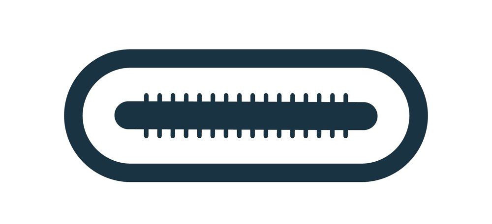
The USB-C pinout accounts for its ability to fulfill a wide swath of power and data roles.
A quarter-century ago, USB burst onto the scene as the grand unification of device peripherals in the computer landscape. Most people no longer had to worry about niche protocols and connectors for various interfacing devices. Within the last decade, USB continued its march as the primary interface for many device interconnections. It has recently been adopted as the standard for cell phone chargers in the EU. To say USB has been anything less than transformative in the peripheral space is an understatement. It is ubiquitous with nearly every electronic device due to its wide range of features and overall prevalence.
Designing hardware or software with USB in mind is a requirement in today’s layout world, and the key to understanding the latest USB connector system is the physical package. USB-C pinout is impressive at first blush due to its mating reversibility, but look underneath, and the staggering ability of the system reveals itself.
The Basics of USB-C Pinout
A vital distinction for USB-C: it refers to the design of the connector and is itself unrelated to the transfer specification. Since form follows function, USB-C is thus far the first and only connector that supports USB4. As visible from its pinout, the receptacle/plug interface is reversible:
|
Pin Des |
A1 |
A2 |
A3 |
A4 |
A5 |
A6 |
A7 |
A8 |
A9 |
A10 |
A11 |
A12 |
|
Pin Name |
GND |
TX1+ |
TX1- |
VBUS |
CC1 |
D1+ |
D1- |
SBU1 |
VBUS |
RX2- |
RX2+ |
GND |
|
GND |
RX1+ |
RX1- |
VBUS |
SBU2 |
D2- |
D2+ |
CC2 |
VBUS |
TX2- |
TX2+ |
GND |
|
|
Pin Des |
B12 |
B11 |
B10 |
B9 |
B8 |
B7 |
B6 |
B5 |
B4 |
B3 |
B2 |
B1 |
The USB Type-C receptacle pinout viewed end-on. The plug pin designators are mirrored horizontally across the center pins alongside slight changes to the pinout.
A quick descriptor of each pin function, by name:
|
GND |
Return plane |
|
TX1/2+ |
Positive high-speed differential pair lines |
|
TX1/2- |
Negative high-speed differential pair lines |
|
VBUS |
Power |
|
CC1/2 |
Channel config |
|
D1/2+ |
Positive USB 2.0 differential pair |
|
D1/2- |
Negative USB 2.0 differential pair |
|
SBU1/2 |
Sideband use |
|
RX1/2- |
Negative high-speed differential pair lines |
|
RX1/2+ |
Positive high-speed differential pair lines |
Alternatively, the plug for USB-C pinout substitutes the channel config pin on B5 gets substituted for a VCONN pin to enable power delivery services. The B6 and B7 pins are also removed, and the second USB 2.0 differential data lines go unreplaced.
One of the most compelling features of USB-C is the number of operating modes available. Since it is comparatively more robust in pin count and functionality than older physical USB systems, it can handily cover depreciated protocols without needing an intermediate translation. This news is welcome for users interfacing with older devices and systems, but USB-C offers much more than compatibility with legacy standards. The gains in transfer speeds mean that newer, modern protocols can also be supported for audiovisual purposes with a single connector system.
USB Operating Modes: Power and Compatibility
USB 2.0
A simple pinout configuration, USB 2.0 mode allows for transfer using the basic differential pair topology. While the protocol is supported by USB 2.0, the physical interface between USB-C and 2.0 requires an adapter due to the differing pin count and receptacle/plug mating. Care should be taken when using A/B to C adapters as A/B plug and C receptacle combinations are invalid and undefined by the USB Implementers Forum. A mismatched pull-up resistor can cause devices to draw more power above maximum ratings, resulting in damage to devices and a potential safety hazard.
One notable advantage of 2.0 is the simpler transfer technology allows for longer cable lengths. A USB-C cable without the Tx/Rx lines can be up to four times as long as cables that support the full scope of USB-C capabilities.
|
Pin Des |
A1 |
A2 |
A3 |
A4 |
A5 |
A6* |
A7* |
A8 |
A9 |
A10 |
A11 |
A12 |
|
Pin Name |
GND |
VBUS |
D1+ |
D1- |
VBUS |
GND |
||||||
|
GND |
VBUS |
VBUS |
GND |
|||||||||
|
Pin Des |
B12 |
B11 |
B10 |
B9 |
B8 |
B7* |
B6* |
B5 |
B4 |
B3 |
B2 |
B1 |
*: Only one USB 2.0 differential pair can be active at any one time in this mode. Because of the reversibility of USB-C, B6/7 could be utilized instead of A6/7.
USB 3.x
USB 3.x topologies utilize one or both of the high-speed differential pairs to realize bitrates much greater than the standard data lines of USB 2.0. USB-C connectors were developed and introduced alongside USB 3.1. All 3.1 and later cables natively support USB-C, including the most recent USB4 standard. 3.1+ and later standards can also output additional current at 1.5/3A.
|
Pin Des |
A1 |
A2* |
A3* |
A4 |
A5* |
A6† |
A7† |
A8 |
A9 |
A10* |
A11* |
A12 |
|
Pin Name |
GND |
TX1+ |
TX1- |
VBUS |
CC1 |
VBUS |
GND |
|||||
|
GND |
RX1+ |
RX1- |
VBUS |
VBUS |
GND |
|||||||
|
Pin Des |
B12 |
B11* |
B10* |
B9 |
B8 |
B7† |
B6† |
B5* |
B4 |
B3* |
B2* |
B1 |
*: For single-lane mode, only the differential pairs closest to the active channel config pin will be in use. Double-lane mode utilizes channel config pins and the four Tx/Rx differential pairs.
†: The USB 2.0 differential pairs generally go unused in USB 3.x mode, but certain devices can operate simultaneously or use the USB 2.0 differential pairs as backup lines in case of a USB 3.x transmission failure.
USB Power Delivery
Power delivery can provide power far above most USB standards: 20V/5A with specialty cables (or 20V/3A as the default specification). The Power Delivery mode is compatible with any data protocol provided one of the two CC pins is available, allowing for simultaneous power and data transfer.
|
Pin Des |
A1 |
A2 |
A3 |
A4 |
A5* |
A6 |
A7 |
A8 |
A9 |
A10 |
A11 |
A12 |
|
Pin Name |
GND |
VBUS |
CC1 |
VBUS |
GND |
|||||||
|
GND |
VBUS |
VBUS |
GND |
|||||||||
|
Pin Des |
B12 |
B11 |
B10 |
B9 |
B8 |
B7 |
B6 |
B5* |
B4 |
B3 |
B2 |
B1 |
*: Only one of the channel config pins are utilized in Power Delivery mode, but once again the reversibility of the USB-C system requires either A5 or B5 (but not both) during operation.
Additional Functionality and Support for USB-C Connectors
Alternate Mode
USB-C provides many exciting features. Still, perhaps none is more valuable to layout designers than the ability to replace a variety of ports with USB-C through Alternate Mode partnerships. Theoretically, this greatly reduces the complexity of routing and conserves land pattern space, an extremely valuable solution for modern HDI designs.
Supported interfaces include:
- DisplayPort: Primarily functions as a packetized audiovisual format, though it can send other forms of data.
- Mobile High-Definition Link: An audiovisual standard established between portable devices and televisions, projectors, etc., to piggyback existing connectors to avoid the need for additional connectors in small devices.
- Thunderbolt: Similar to USB, it combines multiple serial data transfer protocols (PCIe and DisplayPort) and power all on one cable. The most recent Thunderbolt revisions have adopted USB-C as their connector system.
- HDMI: Analog format for transferring video and audio, with additional support for digital audio output.
|
Pin Des |
A1 |
A2 |
A3 |
A4 |
A5* |
A6* |
A7* |
A8 |
A9 |
A10 |
A11 |
A12 |
|
Pin Name |
GND |
TX1+ |
TX1- |
VBUS |
CC1 |
D1+ |
D1- |
SBU1 |
VBUS |
RX2- |
RX2+ |
GND |
|
GND |
RX1+ |
RX1- |
VBUS |
SBU2 |
VBUS |
TX2- |
TX2+ |
GND |
||||
|
Pin Des |
B12 |
B11 |
B10 |
B9 |
B8 |
B7* |
B6* |
B5* |
B4 |
B3 |
B2 |
B1 |
*: Alternate mode allows for USB 2.0 differential pair transfer. Like in USB 2.0 proper, only one pair can be active at a time.
Audio Adapter
USB-C can support audio output from an on-device ADC or one within the adapter. Similar to other modes, device charging is allowed while using Audio Adapter, but only at USB 2.0 levels (5V/500mA) as the channel config pins are in use.
|
Pin Des |
A1 |
A2 |
A3 |
A4 |
A5* |
A6* |
A7* |
A8* |
A9 |
A10 |
A11 |
A12 |
|
Pin Name |
GND |
VBUS |
CC1 |
R |
L |
MIC |
VBUS |
GND |
||||
|
GND |
VBUS |
AGND |
CC2 |
VBUS |
GND |
|||||||
|
Pin Des |
B12 |
B11 |
B10 |
B9 |
B8* |
B7* |
B6* |
B5* |
B4 |
B3 |
B2 |
B1 |
*: Audio Adapter mode places the audio channel on one of the two USB 2.0 differential pairs, dependent on the orientation of the receptacle.
Debug
Debug mode allows engineers to test accessories by pulling the CC pins, either both high or low. Once entered, Power Delivery mode can be set up and results in the pinout shown below. All digital circuits are disconnected in this configuration to analyze the signal pins of the seven differential pairs.
|
Pin Des |
A1 |
A2* |
A3* |
A4* |
A5 |
A6* |
A7* |
A8 |
A9 |
A10* |
A11* |
A12 |
|
Pin Name |
GND |
TX1+ |
TX1- |
VBUS |
CC1 |
D1+ |
D1- |
SBU1 |
VBUS |
RX2- |
RX2+ |
GND |
|
GND |
RX1+ |
RX1- |
VBUS |
SBU2 |
D2- |
D2+ |
CC2 |
VBUS |
TX2- |
TX2+ |
GND |
|
|
Pin Des |
B12 |
B11* |
B10* |
B9 |
B8* |
B7* |
B6* |
B5 |
B4 |
B3* |
B2* |
B1 |
All digital circuits are disconnected in this configuration to analyze the signal pins of the seven differential pairs. Debugging can be performed on all 14 lines when Power Delivery is active. When Power Delivery is not in use, seven test signal lines are available instead (TS1=A2/B2, TS2 = A3/B3, etc.)
The key to unlocking the potential of the most recent USB connector system is understanding the USB-C pinout and what features each mode can support. As much as end users enjoy the flexibility of an all-inclusive connector, designers benefit even more from a streamlined approach in compact layouts. Given the importance of the connector to a wealth of device applications, ensuring the quality of its associated land pattern can be the difference between a PCB assembly and testing progressing smoothly or requiring rework or revision.
Ultra Librarian assists design teams by providing an online library of millions of component footprints for popular ECAD toolsets. With a host of verified land patterns, layout teams can place components worry-free and turn their efforts towards optimizing performance. If you’re looking for CAD models for common components or helpful design information like USB C pinout requirements, Ultra Librarian helps by compiling all your sourcing and CAD information in one place.
Working with Ultra Librarian sets up your team for success to ensure streamlined and error-free design, production, and sourcing. Register today for free.


