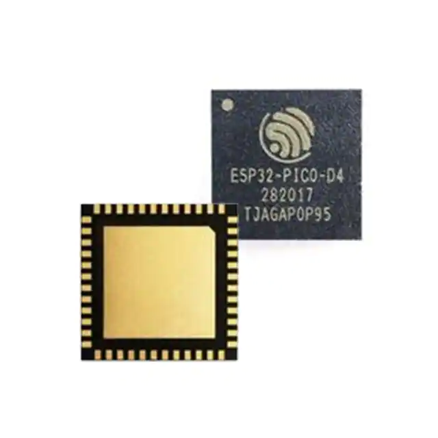
Image of Espressif Systems’s ESP32-PICO-D4 SiP module (Source: DigiKey)
A system-in-package (SiP) module is an advanced electronic packaging technology that integrates multiple integrated circuits (ICs) or other components. It combines various functions like microprocessors, memory, sensors, and communication interfaces into a compact and highly integrated module. SiP modules are crucial in miniaturizing electronic devices, improving performance, optimizing power consumption, and developing increasingly advanced and feature-rich electronics.
Espressif Systems is a leader in manufacturing SiP modules. One of their popular modules, ESP32-PICO-D4, is described in this datasheet.
ESP32-PICO-D4: Applications and Features:
The ESP32-PICO-D4 is a SiP module that provides Wi-Fi and Bluetooth functionalities and is based on the ESP32 chip, which is a single 2.4 GHz Wi-Fi and Bluetooth combo chip using ultra-low power technology. In one package, the module integrates peripheral components, such as crystal oscillators, flash, filter capacitors, and RF matching links. Module welding and testing are not required.
ESP32-PICO-D4 Applications:
- Mobile devices
- Wearable electronics
- Medical equipment
- Wi-Fi-enabled toys
- Sensors
- Cameras
- Audio headsets
- Home automation
- Smart buildings
- Internet of Things products
As the list above indicates, the ESP32-PICO-D4 is a versatile SiP module that can be used in a variety of products.
Using the ESP32-PICO-D4 Datasheet
Using ESP32-PICO-D4, you can improve control efficiency and reduce supply chain complexity. This SiP module is well suited for applications that require low power consumption, compact size, and strong performance, including wearable electronics, medical equipment, sensors, and other IoT applications.
Before designing your PCB, it is crucial to consult the ESP32-PICO-D4 datasheet for necessary specifications, which are included below.
Important ESP32-PICO-D4 Specifications
|
ESP32-PICO-D4 DATASHEET SPECIFICATIONS |
||
|
Categories |
Items |
Specifications |
|
Certifications |
Bluetooth certification |
BQB |
|
Wi-Fi |
Protocols |
802.11 b/g/n (802.11n up to 150 Mbps) |
|
A-MPDU and A-MSDU aggregation and 0.4 µs guard interval support |
||
|
Center frequency range of operating channel |
2412 ~ 2484 MHz |
|
|
Bluetooth |
Protocols |
Bluetooth V4.2 BR/EDR and Bluetooth LE specification |
|
Radio |
NZIF receiver with –97 dBm sensitivity |
|
|
Class-1, class-2 and class-3 transmitter |
||
|
AFH |
||
|
Audio |
CVSD and SBC |
|
|
Hardware |
Module interfaces |
ADC, DAC, touch sensor, SD/SDIO/MMC Host Controller, SPI, SDIO/SPI Slave Controller, EMAC, motor PWM, LED PWM, UART, I2C, I2S, infrared remote controller, GPIO, pulse counter, TWAI® (compatible with ISO 11898-1, i.e.CAN Specification 2.0) |
|
On-chip sensor |
Hall sensor |
|
|
Integrated crystal |
40 MHz crystal |
|
|
Integrated SPI flash |
4 MB |
|
|
Operating voltage/Power supply |
3.0 V ~ 3.6 V |
|
|
Operating current |
Average: 80 mA |
|
|
Minimum current delivered by power supply |
500 mA |
|
|
Operating ambient temperature |
–40 °C ~ 85 °C |
|
|
Package size |
(7.000±0.100) mm×(7.000±0.100) mm×(0.940±0.100) mm |
|
|
Moisture sensitivity level |
Level 3 |
|
ESP32-PICO-D4 Datasheet Specifications (Source: Espressif Systems)
ESP32-PICO-D4 Pin Layout and Definitions
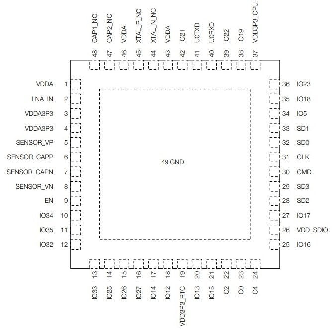
The pin layout of the ESP32-PICO-D4 is shown in the figure below.

ESP32-PICO-D4 Pin Layout – Top View (Source: Espressif Systems)
The ESP32-PICO-D4 module has 48 pins. See pin definitions below:
|
Name |
No. |
Type |
Function |
|
VDAA |
1 |
P |
Analog power supply (2.3 V ~ 3.6 V) |
|
LNA_IN |
2 |
I/O |
RF input and output |
|
VDDA3P3 |
3 |
P |
Analog power supply (2.3 V ~ 3.6 V) |
|
VDDA3P3 |
4 |
P |
Analog power supply (2.3 V ~ 3.6 V) |
|
SENSOR_VP |
5 |
I |
GPIO36, ADC1_CH0, RTC_GPIO0 |
|
SENSOR_CAPP |
6 |
I |
GPIO37, ADC1_CH1, RTC_GPIO1 |
|
SENSOR_CAPN |
7 |
I |
GPIO38, ADC1_CH2, RTC_GPIO2 |
|
SENSOR_VN |
8 |
I |
GPIO39, ADC1_CH3, RTC_GPIO3 |
|
EN |
9 |
I |
High: On; enables the module Low: Off; the module powers off Note: Do not leave this pin floating. |
|
IO34 |
10 |
I |
GPIO34, ADC1_CH6, RTC_GPIO4 |
|
IO35 |
11 |
I |
GPIO35, ADC1_CH7, RTC_GPIO5 |
|
IO32 |
12 |
I/O |
GPIO32, 32K_XP (32.768 kHz crystal oscillator input), ADC1_CH4, TOUCH9, RTC_GPIO9 |
|
IO33 |
13 |
I/O |
GPIO33, 32K_XN (32.768 kHz crystal oscillator output), ADC1_CH5, TOUCH8, RTC_GPIO8 |
|
IO25 |
14 |
I/O |
GPIO25, DAC_1, ADC2_CH8, RTC_GPIO6, EMAC_RXD0 |
|
IO26 |
15 |
I/O |
GPIO26, DAC_2, ADC2_CH9, RTC_GPIO7, EMAC_RXD1 |
|
IO27 |
16 |
I/O |
GPIO27, ADC2_CH7, TOUCH7, RTC_GPIO17, EMAC_RX_DV |
|
IO14 |
17 |
I/O |
GPIO14, ADC2_CH6, TOUCH6, RTC_GPIO16, MTMS, HSPICLK, HS2_CLK, SD_CLK, EMAC_TXD2 |
|
IO12 |
18 |
I/O |
GPIO12, ADC2_CH5, TOUCH5, RTC_GPIO15, MTDI, HSPIQ, HS2_DATA2, SD_DATA2, EMAC_TXD3 |
|
VDD3P3_RTC |
19 |
P |
Input power supply for RTC IO (3.0 V ~ 3.6 V) |
|
IO13 |
20 |
I/O |
GPIO13, ADC2_CH4, TOUCH4, RTC_GPIO14, MTCK, HSPID, HS2_DATA3, SD_DATA3, EMAC_RX_ER |
|
IO15 |
21 |
I/O |
GPIO15, ADC2_CH3, TOUCH3, RTC_GPIO13, MTDO, HSPICS0, HS2_CMD, SD_CMD, EMAC_RXD3 |
|
IO2 |
22 |
I/O |
GPIO2, ADC2_CH2, TOUCH2, RTC_GPIO12, HSPIWP, HS2_DATA0, SD_DATA0 |
|
IO0 |
23 |
I/O |
GPIO0, ADC2_CH1, TOUCH1, RTC_GPIO11, CLK_OUT1, EMAC_TX_CLK |
|
IO4 |
24 |
I/O |
GPIO4, ADC2_CH0, TOUCH0, RTC_GPIO10, HSPIHD, HS2_DATA1, SD_DATA1, EMAC_TX_ER |
|
IO16 |
25 |
I/O |
GPIO16, HS1_DATA4, U2RXD, EMAC_CLK_OUT |
|
VDD_SDIO |
26 |
P |
Output power supply. |
|
IO17 |
27 |
I/O |
GPIO17, HS1_DATA5, U2TXD, EMAC_CLK_OUT_180 |
|
SD2 |
28 |
I/O |
GPIO9, SD_DATA2, SPIHD, HS1_DATA2, U1RXD |
|
SD3 |
29 |
I/O |
GPIO10, SD_DATA3, SPIWP, HS1_DATA3, U1TXD |
|
CMD |
30 |
I/O |
GPIO11, SD_CMD, SPICS0, HS1_CMD, U1RTS |
|
CLK |
31 |
I/O |
GPIO6, SD_CLK, SPICLK, HS1_CLK, U1CTS |
|
SD0 |
32 |
I/O |
GPIO7, SD_DATA0, SPIQ, HS1_DATA0, U2RTS |
|
SD1 |
33 |
I/O |
GPIO8, SD_DATA1, SPID, HS1_DATA1, U2CTS |
|
IO5 |
34 |
I/O |
GPIO5, VSPICS0, HS1_DATA6, EMAC_RX_CLK |
|
IO18 |
35 |
I/O |
GPIO18, VSPICLK, HS1_DATA7 |
|
IO23 |
36 |
I/O |
GPIO23, VSPID, HS1_STROBE |
|
VDD3P3_CPU |
37 |
P |
Input power supply for CPU IO (1.8 V ~ 3.6 V) |
|
IO19 |
38 |
I/O |
GPIO19, VSPIQ, U0CTS, EMAC_TXD0 |
|
IO22 |
39 |
I/O |
GPIO22, VSPIWP, U0RTS, EMAC_TXD1 |
|
U0RXD |
40 |
I/O |
GPIO3, U0RXD, CLK_OUT2 |
|
U0TXD |
41 |
I/O |
GPIO1, U0TXD, CLK_OUT3, EMAC_RXD2 |
|
IO21 |
42 |
I/O |
GPIO21, VSPIHD, EMAC_TX_EN |
|
VDDA |
43 |
P |
Analog power supply (2.3 V ~ 3.6 V) |
|
XTAL_N_NC |
44 |
– |
NC |
|
XTAL_P_NC |
45 |
– |
NC |
|
VDDA |
46 |
P |
Analog power supply (2.3 V ~ 3.6 V) |
|
CAP2_NC |
47 |
– |
NC |
|
CAP1_NC |
48 |
– |
NC |
ESP32-PICO-D4 Pin Description (Source: Espressif Systems)
Optimizing Your ESP32-PICO-D4 PCBA Design
You can find detailed information, such as performance characteristics, on the ESP32-PICO-D4 datasheet in addition to the data presented above.
For the best ESP32-PICO-D4 implementation, the datasheet should be used along with accurate CAD models to help ensure optimal PCBA development.

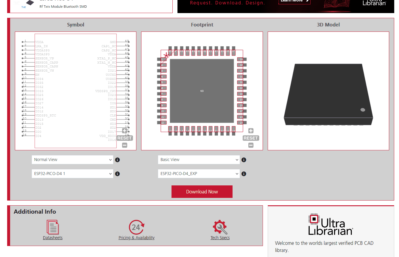
ESP32-PICO-D4 CAD data from UL
For electronic product development to be efficient, your PCBA design and manufacturing stages must be collaborative and supportive. You should begin with a reliable component library where you can be assured of the accuracy of the data and models.
If you’re looking for CAD models for common components or design tips like how to best use the ESP32-PICO-D4 datasheet, Ultra Librarian helps by compiling all your sourcing and CAD information in one place.
Working with Ultra Librarian sets up your team for success to ensure streamlined and error-free design, production, and sourcing. Register today for free.


