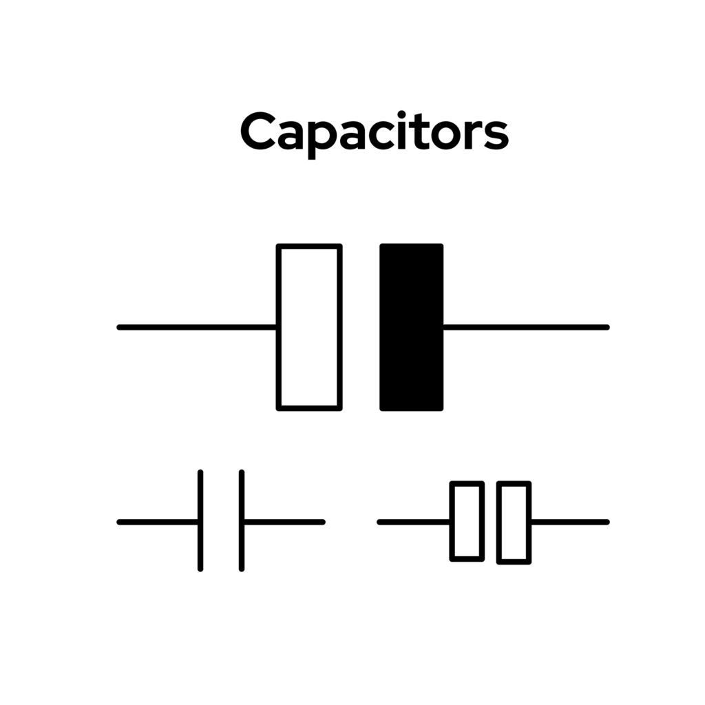
Capacitor symbols
At the most basic level, electronic components are typically described as being either active or passive. This oversimplification is minimally useful for designers of PCBAs. More important is an understanding of the essential functions that different components perform.
For some components; such as capacitors, the range of functionality and different uses are quite extensive. The prevalence of these critical parts on circuit boards necessitate an understanding of the various types essential for effective PCBA design and development. This includes recognizing the many capacitor symbols that are commonly used to distinguish their attributes.
The Important Capacitor Symbols to Know
The term capacitor has only been in use since the 20th century. However, the property that certain devices could store electrical charge, which is fundamental to all capacitors, has been known since the mid 1800’s. This is accomplished with two conductive elements separated by a non-conductive space, which is typically a dielectric material or simply air. This architecture is reflected in virtually all schematic representations of the component; including the commonly used capacitor symbols below.
Various commonly used capacitor symbols
As illustrated above, the use of two geometric shapes–representing conductive plates–separated by space is the defining feature that distinguishes capacitors from other electronic component schematic symbols. Many symbols include a “+” sign to indicate which element should be connected to a positively charged source. The use of an angled line or arrow is also a common feature for specifying the capacitance value is variable.
Capacitor Types and Applications
As discussed above, there are many different symbols for capacitors. Each of these unique graphical representations is intended to convey useful information to ensure that the correct component is implemented for the PCBA design. Fulfilling this objective is dependent on the engineer or designer that chooses or creates the capacitor symbol for the schematic or drawing. Making the most appropriate selections requires understanding the types of capacitors the symbols represent and how they are used.
|
TYPES OF CAPACITORS |
||
|
TYPES |
Description |
Common Application(s) |
|
Polarized capacitors |
Caps that must be used with specific polarities. |
Power supply filtering or to block DC between amplifier stages. |
|
Non-polarized capacitors |
Versatile and polarity independent. |
Decoupling, coupling, oscillation, feedback, etc. |
|
Bipolar capacitors |
Used where polarity can switch from positive and negative. |
Speaker systems and phase shifting in motors |
|
Variable capacitors |
Tunable capacitance devices. |
Frequency tuning and impedance matching |
|
Differential capacitors |
Caps where the capacitance value changes due to some environment or circuit change. |
Sensors |
|
Voltage dependent capacitors |
Devices where the capacitance varies according to the voltage. |
Tunable circuits and for antenna impedance matching. |
|
Temperature dependent capacitors |
Capacitance changes as temperature varies. |
High temperature caps are used in automotive system design applications. |
|
Trimmer capacitors |
Components with adjustable plates that enable capacitance value refinement. |
Stabilizing frequency elements like variable frequency oscillators (VFOs) |
|
Electrolytic capacitors |
Employ electrolyte for higher capacitance values. |
Filtering noise and reducing EMI and decoupling |
|
Ganged capacitors |
Two or more caps physically connected together such that a change in one causes a corresponding change in the other. |
Commonly used in manually tuned radios. |
The table above is not exhaustive. However, it is representative of the most used types of capacitors and their applications. As shown above, capacitors are typically used to block or filter out DC and vary or control signal frequency.
How to Optimize Your Capacitor PCB Design
Although, most circuit boards require these common components, selecting the best capacitor for your design can be a significant challenge. In addition to ensuring the device meets your performance specifications for capacitance value, parameters like dielectric permissivity, temperature, size, shape, and often high-speed PCB layout considerations should influence your decision. However, by following a set of good guidelines, as listed below, you can optimize your capacitor board design.
PCBA Design Optimization with Capacitors
✅ Become familiar with the various types and uses for different capacitors.
✅ Employ commonly used components, if possible.
✅ Use manufacturer datasheets for accurate parametric information.
✅ Only use capacitor symbols that adhere to industry standards.
✅ Use a reliable component library source for capacitor symbols and other CAD models.
Incorporating the guidelines above into your PCBA design best practices will help to ensure the accuracy of your capacitor CAD data and the efficient manufacturing of your board design.
If you’re looking for CAD models for common components or design information, like the important capacitor symbols to know, Ultra Librarian helps by compiling all your sourcing and CAD information in one place.
Working with Ultra Librarian sets up your team for success to ensure streamlined and error-free design, production, and sourcing. Register today for free.