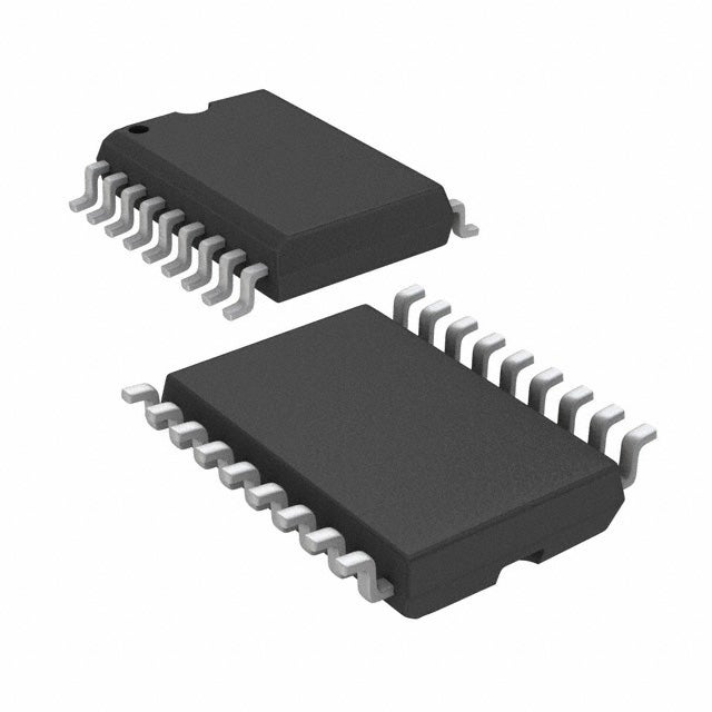
Representations of the ULN2803ADWR Darlington transistor array (Source: DigiKey)
The ULN2803ADWR, made by Texas Instruments, is a high-voltage, high-current Darlington transistor array. Invented by Sidney Darlington in 1953, a Darling transistor configuration has bipolar transistor pairs with the emitter of one transistor connected to the base of the other so that the current amplified by the first transistor is amplified more by the second one. The article below examines the characteristics of the array detailed in the ULN2803ADWR datasheet.
ULN2803ADWR Datasheet: Features and Applications
The ULN2803ADWR has eight negative-positive-negative (NPN) Darlington pairs featuring high-voltage outputs with common-cathode clamp diodes for switching inductive loads. The Darlington pairs can be connected in parallel for higher current capability, and each pair has a collector-current rating of 500 mA.
|
ULN2803ADWR Datasheet: Key Features and Applications |
||
|
Features |
Application |
Importance |
|
✔ 8 Darlington Transistor Arrays |
Used for driving multiple loads simultaneously, such as relays, LEDs, or motors |
Consolidates multiple drivers into a single package, reducing PCB space and simplifying circuit design |
|
✔ 500-mA Rated Collector Current (Single Output) |
Drives high-current loads such as solenoids and motors |
Provides the ability to control high-power devices directly, eliminating the need for additional driver circuits |
|
✔ High-Voltage Output: 50 V |
Suitable for interfacing with high-voltage components and systems |
Ensures compatibility with a wide range of loads and allows operation in systems with higher voltage requirements |
|
✔ Internal Freewheeling Diodes |
Protects against voltage spikes caused by inductive loads like motors and relays |
Enhances reliability and longevity of the circuit by protecting against back electromagnetic fields |
|
✔ Inputs Compatible With Various Types of Logic |
Direct interfacing with microcontrollers, microprocessors, and other logic circuits |
Facilitates easy integration with digital systems, simplifying design and ensuring reliable operation |
The ULN2803ADWR is a smart choice for solenoids, relays, lamps, small motors, and display drivers (light-emitting diode and gas discharge). Paralleling outputs can serve applications that require sink currents beyond the capability of a single output.
ULN2803ADWR: PIN Configurations and Functional Block Diagram
The figures below present the PIN configurations and functions of the ULN2803ADWR.
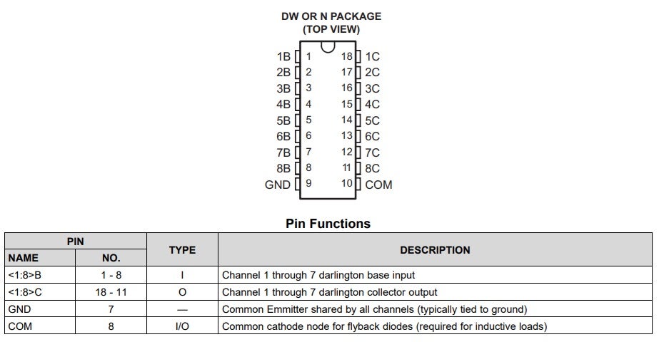
ULN2803ADWR Pin Configuration and Functions
The ULN2803ADWR provides a high output current drive with a very low input current, which equates to a low general-purpose input/output (GPIO) voltage. The GPIO voltage is converted to base current through the 2.7 kΩ resistor connected between the pre-driver Darlington NPN’s input and base. The 7.2 kΩ and 3 kΩ resistors connected between the base and the emitter of each NPN suppress the leakage that may occur from the input.
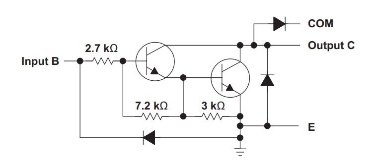
ULN2803ADWR Functional Block Diagram
In typical operation, the diodes on the base and the collector pins to the emitter are reversed-biased. If these diodes are forward-biased, internal parasitic NPN transistors draw a nearly equal current from other pins.
ULN2803ADWR: Maximum Ratings
A Darlington transistor’s maximum ratings are essential for PCB designers to know because they define the operational limits within which the transistor can function without risking damage or failure. Below are the absolute maximum ratings for the ULN2803ADWR as presented in the datasheet:

ULN2803ADWR Absolute Maximum Ratings
The thermal and electrical characteristics of Darlington transistors are also important to know because they enable PCB designers to select and integrate transistors into their designs while ensuring optimal performance and reliability. The datasheet shows these characteristics of the ULN2803ADWR.

ULN2803ADWR Thermal Characteristics
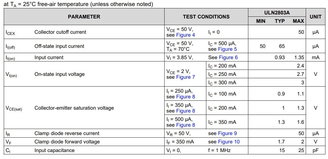
ULN2803ADWR Electrical Characteristics
Below are the figures referred to in the ULN2803ADWR Electrical Characteristics table:
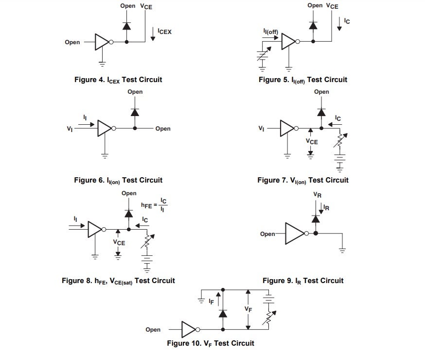
ULN2803ADWR Parameter Measurement Data
By considering thermal and electrical properties, designers can design PCB layouts and incorporate thermal management strategies that maximize the efficiency, reliability, and lifespan of the electronic systems they develop.
PCB Design With the ULN2803ADWR Datasheet
In addition to the characteristics above, the ULN2803ADWR datasheet provides more information for your PCB layout design. As shown in the schematic, footprint, and 3D model below, your component’s CAD model and data must be accurate and from a trusted database to be helpful.
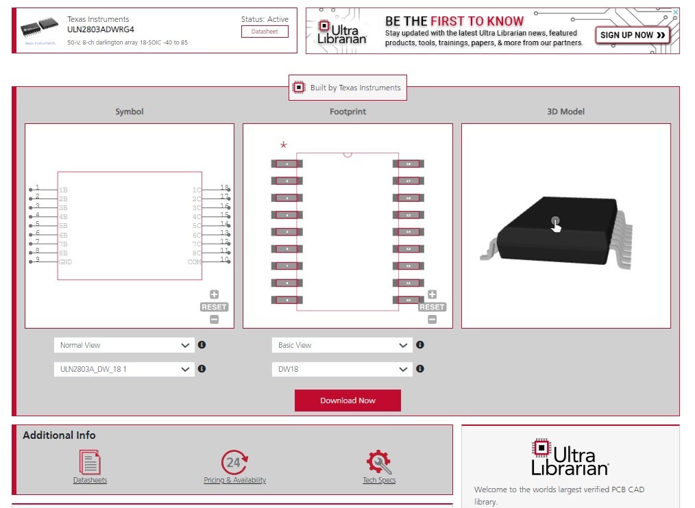
ULN2803ADWR schematic symbol, footprint, and 3D CAD model from UL
By combining manufacturer PCB layout data with the components’ specifications, characteristics, and performance metrics in their datasheets, you can design your PCB effectively and efficiently.
If you’re looking for CAD models for common components or more information on the ULN2803ADWR datasheet, Ultra Librarian compiles all your sourcing and CAD information in one place.
Working with Ultra Librarian sets up your team for success to ensure streamlined and error-free design, production, and sourcing. Register today for free.


