
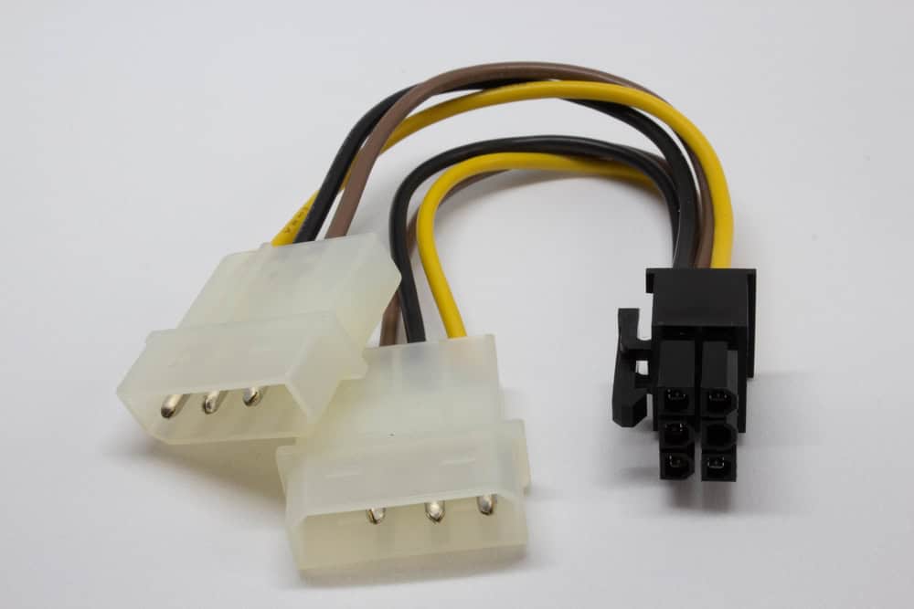
PCIe power connector cable
Peripheral Component Interconnect Express (PCIe) cards and connectors have been commonly used in many electronics products; such as computers and peripherals, for many years. The PCIe designation was introduced in 2003 by PCI-SIG, the Peripheral Component Interconnect Express Special Interest Group. The group is comprised of primarily microelectronics industry companies and seeks to establish compliance specifications to ensure reliable operation between devices that utilize PCIe components.
PCIe cards are often used in computers and other devices as expansion slots to add functionality and/or capability. PCIe connectors are used to connect to peripherals; however, they are also used to connect internal system elements. One of the chief internal usages is to supply power to boards and other devices. To ensure reliable operation, it is important to employ best practices for PCIe power pin layout design.
Types of PCIe Power Connectors
The most commonly implemented PCIe power connectors are the 6-pin and 8-pin, listed below.


* Specified is the power standard by PCI-SIG. Rated power is the device power rating.
As shown above, the 6-pin PCIe connectors provide two 12 V sources for DC power, while the 8-pin connectors deliver three 12 V ports for power draw. The sense pins are important as they inform the card or device that power is available, and at what level. For example, low Sense and Sense1, for 6-pin and 8-pin, respectively, indicate 75W, while low Sense1 indicates 150 W for 8-pin connections.
As power requirements for computing systems and other devices have increased, the use of multiple 6- or 8-pin power cables has grown. Additionally, the 12V-2×6, a revision of the 12VHPWR connector specification introduced in 2022, specifically to address the high-power needs of graphics processing units (GPUs), provides up to 600 W as specified by PCI-SIG for compliance.
PCB Design for PCIe Components
When designing circuit boards that utilize PCIe components, it is important to follow good PCIe routing guidelines. These include careful consideration of the following:
Important PCIe Power Pin Layout Design Considerations
- Component spacing
- Following component spacing standards is critical to prevent interference between power and signal traces that can disrupt operation and significantly degrade board performance.
- Trace spacing and clearance
- Many PCIe devices carry high-speed signals; therefore, it is essential that adequate trace spacing and clearance rules and guidelines are followed.
- Electromagnetic interference (EMI)
- When high-speed data TX/RX is coupled with high-power consumption, the potential for unwanted radiation or EMI is a major concern. Consequently, taking steps to maximally reduce noise and ground loops are mandatory design activities.
- Thermal analysis
- Another important consideration for high-power devices and PCBs is excess heat. High heat without adequate dissipation can lead to component and/or board damage. Therefore, performing thermal analysis for components and power distribution network (PDN) simulation is highly recommended.
Incorporating the guidelines above into your design process will help you avoid contingencies that may be rooted in PCIe power pin layout issues.
Ensuring Accurate PCIe Power Pin Layout
PCIe boards and connectors perform invaluable functions in and between electronic devices and systems. PCIe connectors provide engineers and PCB designers with a standardized, yet flexible means of ensuring adequate power is available and reliably transferred to high-performance components and devices. Realizing the benefits of these components requires following guidelines for PCIe power pin layout design, as listed below.
By employing the list of guidelines above, you are significantly reducing the possibility of any performance or reliability issues during the lifecycle of your board due to PCIe component or connector concerns.
If you’re looking for CAD models for common components or important design information like how to best design your PCIe power pin layout, Ultra Librarian helps by compiling all your sourcing and CAD information in one place.
Working with Ultra Librarian sets up your team for success to ensure streamlined and error-free design, production, and sourcing. Register today for free.


