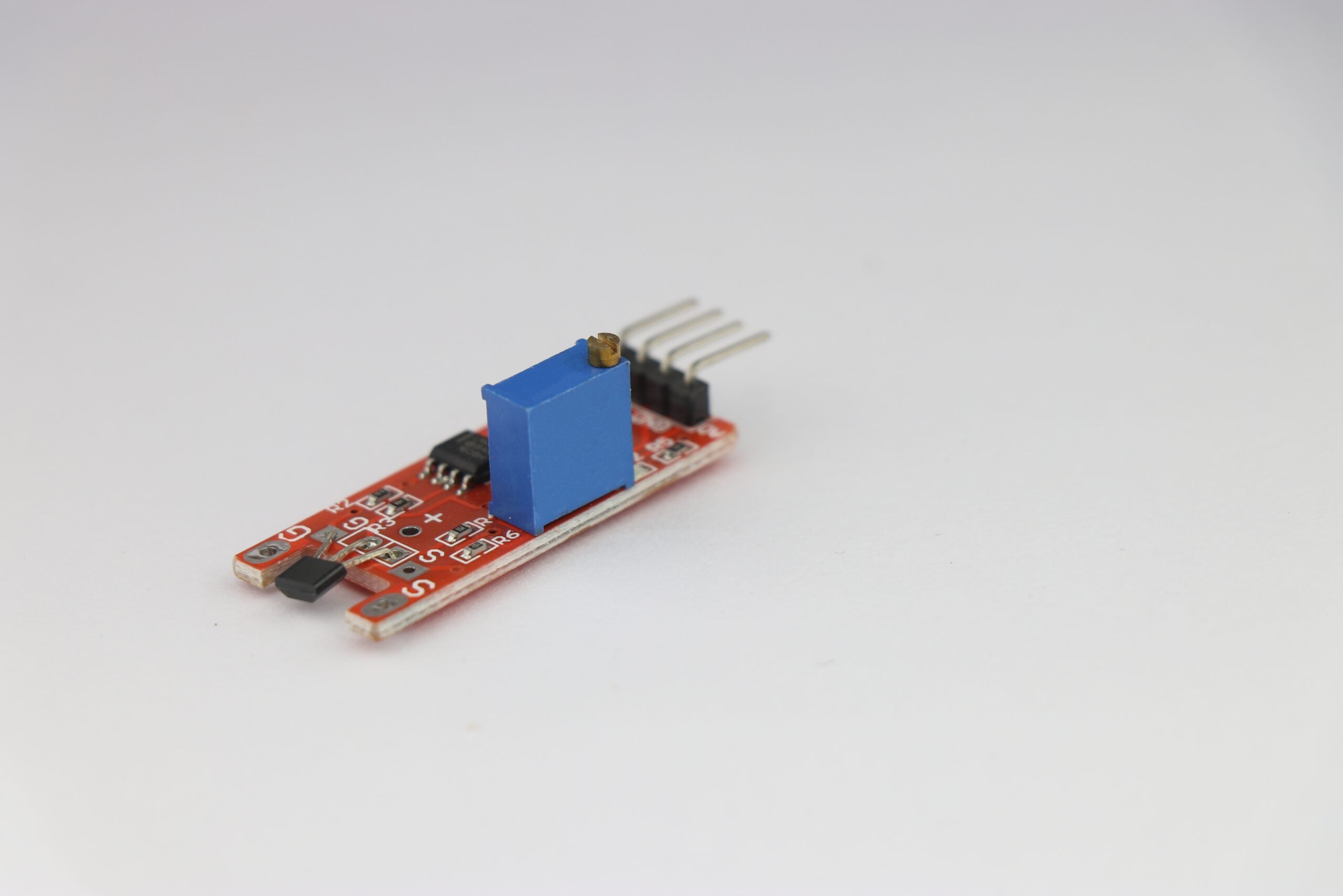
Linear hall effect sensor module
Hall effect sensors detect magnetic fields based on the Hall effect, which occurs when a magnetic field perpendicular to a current-carrying conductor creates a voltage across it. This sensor converts magnetic fields into electrical signals that are used for proximity sensing, position detection, and measurement of current. Engineers developing automotive systems, industrial automation, and consumer electronics often use Hall effect sensors because of their reliability and ability to function without physical contact.How to Choose Hall Effect Sensors
The selection of the right Hall effect sensors for your project affects system accuracy, efficiency, and reliability. The sensor needs to match the application’s requirements, which can include magnetic field sensitivity, digital or analog output voltage/current, temperature operation range, and interference tolerance. For example, a sensor that can withstand harsh conditions and detect precise magnetic field changes is essential for the safety and performance of automotive systems. Using the wrong sensor can lead to inaccurate readings, increased power consumption, or even device failure. The table below describes some best practices for picking Hall effect sensors.|
Criteria for Selecting Hall Effect Sensors |
|
|
Criteria |
Best Practice |
|
Magnetic Range |
Choose sensors with a range compatible with the magnetic field strength in your application. |
|
Sensitivity |
Select sensitivity based on the application’s detection range—higher sensitivity for weak fields, lower for stronger fields. |
|
Power Consumption |
Opt for low-power sensors for battery-operated or energy-sensitive designs. |
|
Operating Voltage |
Ensure the sensor’s voltage range matches the system’s power supply (typically 3.3V or 5V for most PCBs). |
|
Output Type |
Choose between analog (proportional output) and digital (threshold-based switch) sensors, depending on your signal requirements. |
|
Response Time |
Select a sensor with a quick response time for applications needing fast detection. |
|
Temperature Range |
Pick sensors rated for the temperature range of your environment, especially for industrial or automotive applications. |
|
Package Size and Type |
Ensure the sensor package (surface-mount or through-hole) fits the available PCB space and is compatible with your assembly process. |
|
Mounting Considerations |
Choose sensors with the correct mounting orientation and positioning flexibility, based on the magnetic field’s direction. |
|
EMI Considerations |
Look for sensors with built-in shielding or filtering features to mitigate electromagnetic interference (EMI). |
|
Cost and Availability |
Factor in the sensor’s price and availability, especially for mass production. Choose widely used and well-supported sensors. |
|
Supplier Support and Documentation |
Select sensors from suppliers offering comprehensive datasheets, reference designs, and software libraries. |
|
Industry Certifications |
Check for sensors that meet certifications (such as AEC-Q100 for automotive, ISO for industrial) if required. |
|
Sensing Type |
Decide between unipolar, bipolar, omnipolar, or linear Hall sensors based on whether you need to detect one or both polarities or require proportional output. |
Types of Hall Effect Sensors
As can be seen in the last criteria of the above table, Hall effect sensors come in a variety of sensing types, each designed for different applications based on how they respond to magnetic fields and their output. Here is an explanation of each type with an example.- Unipolar Hall Effect Sensors detect only one magnetic pole and switch on when exposed to it. They are used for on/off switching applications, such as position sensing or limit switches.
- Bipolar Hall Effect Sensors require both the north and south magnetic poles to switch on and off. They are used in applications that need to detect a polarity change, such as in rotational speed sensors.
- Omnipolar Hall Effect Sensors can be activated by either magnetic pole (north or south), providing more flexibility in detection. They are used in applications where the magnet’s orientation isn’t fixed, like in proximity sensing.
- Latch Hall Effect Sensors remain latched on after exposure to one pole and can only switch off when exposed to the opposite pole. They are used in motor commutation and rotary encoder applications.
- Linear Hall Effect Sensors produce an analog output proportional to the strength of the magnetic field. They are used in applications requiring precise field strength measurements, such as current and position sensing and fluid level monitoring.
- Digital Hall Effect Sensors output a simple on/off (high/low) signal based on the presence of a magnetic field, making them useful for applications where binary detection is sufficient, like in digital switches and encoders.