Free Online PCB CAD Library

LM3481 Datasheet: Analysis and Evaluation

Texas Instruments’ LM3481 high-efficiency controller Low-side N-FET high-performance controllers are electronic circuits that control the switching of N-channel MOSFETs (N-FETs) connected to the ground side of load in applications like power management, motor control, and DC-DC converters. These controllers drive the gate of the N-FET, allowing it to turn on and off rapidly, thereby managing power delivery with minimal losses. Its high-performance characteristics, such as fast switching times and low on-resistance, make it best for applications requiring efficient energy conversion and thermal management. A commonly used low-side N-FET high-performance controller is the LM3481. It is employed in boost converters, single-ended primary-inductor converters (SEPIC), and flyback converters and topologies that need a low-side FET as the primary switch. For the best PCB design, engineers should leverage information, such as features, applications, and specifications, from Texas Instruments’ LM3481 datasheet

LM3481 Datasheet: Features and Applications

The LM3481 is a versatile low-side N-FET high-performance controller for switching regulators. Its features and applications, as described in the datasheet, are listed below.

IMPORTANT LM3481 FEATURES & APPLICATIONS

Features

Applications

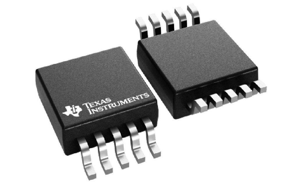
✔ 10-lead VSSOP package

+ Boost for audio amplifiers in portable speakers

✔ Internal push-pull driver with 1A peak current capability

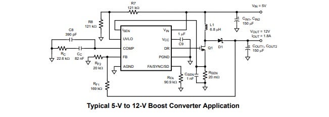
+ Wide input boost, SEPIC, and flyback power modules

✔ Current limit and thermal shutdown

+ Isolated supply (flyback)

✔ Frequency compensation optimized with a capacitor and a resistor

+ Battery-powered boost, SEPIC, and flyback

✔ Internal soft start

✔ Current mode operation

✔ Adjustable undervoltage lockout with hysteresis

✔ Pulse skipping at light loads

A boost converter is a typical application for LM3481. Here is a diagram from the datasheet showing the boost converter configuration. The LM3481 can operate at very high switching frequencies. A single external resistor or an external clock can be used to adjust the switching frequency of the LM3481 to values between 100 kHz and 1 MHz. With the use of current mode control, engineers can achieve superior bandwidth and transient response, as well as cycle-by-cycle current limiting. A single external resistor can be used to set the current limit.

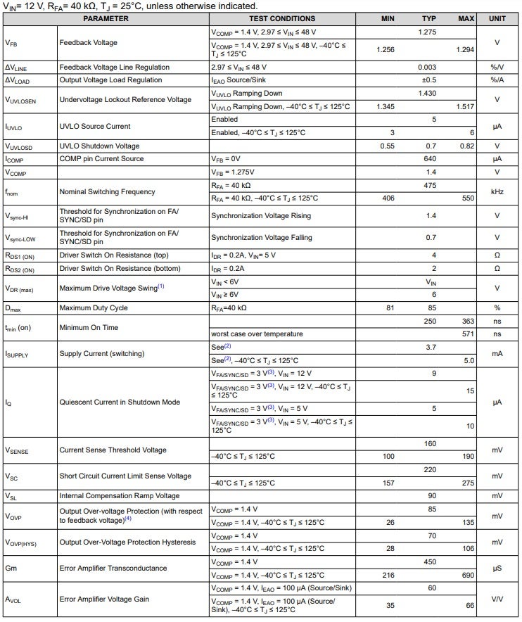
LM3481: Parameters and Specifications

According to the datasheet, the LM3481 has the following absolute maximum electrical and thermal ratings:

ABSOLUTE MAXIMUM RATINGS (over operating free-air temperature range)

MIN

MAX

UNIT

VIN

Pin Voltage

−0.4

50

V

FB

Pin Voltage

−0.4

6

V

FA/SYNC/SD

Pin Voltage

−0.4

6

V

COMP

Pin Voltage

−0.4

6

V

UVLO

Pin Voltage

−0.4

6

V

VCC

Pin Voltage

−0.4

7

V

ISEN

Pin Voltage

−400

600

mV

Peak Driver

1

A

Output Current

Power Dissipation

Internally Limited

Internally Limited

Junction Temperature

150span>

Lead Temperature (only applies to operating conditions)

DGS Package

220

Peak Body Temperature

260

TSTG

Storage Temperature Range

-65

150

The electrical characteristics of high-efficiency controllers directly affect the performance, reliability, and energy consumption of electronic systems. These controllers regulate power delivery, optimize energy usage, and ensure that electronic components operate within safe parameters. Knowledge of their electrical properties enables engineers to design more efficient circuits, reduce heat generation, and extend the lifespan of components. Below are the electrical characteristics for the LM3481 from the datasheet. LM3481 ELECTRICAL CHARACTERISTICS Understanding electrical characteristics also aids in compliance with industry standards, leading to more sustainable and cost-effective solutions in a range of applications.

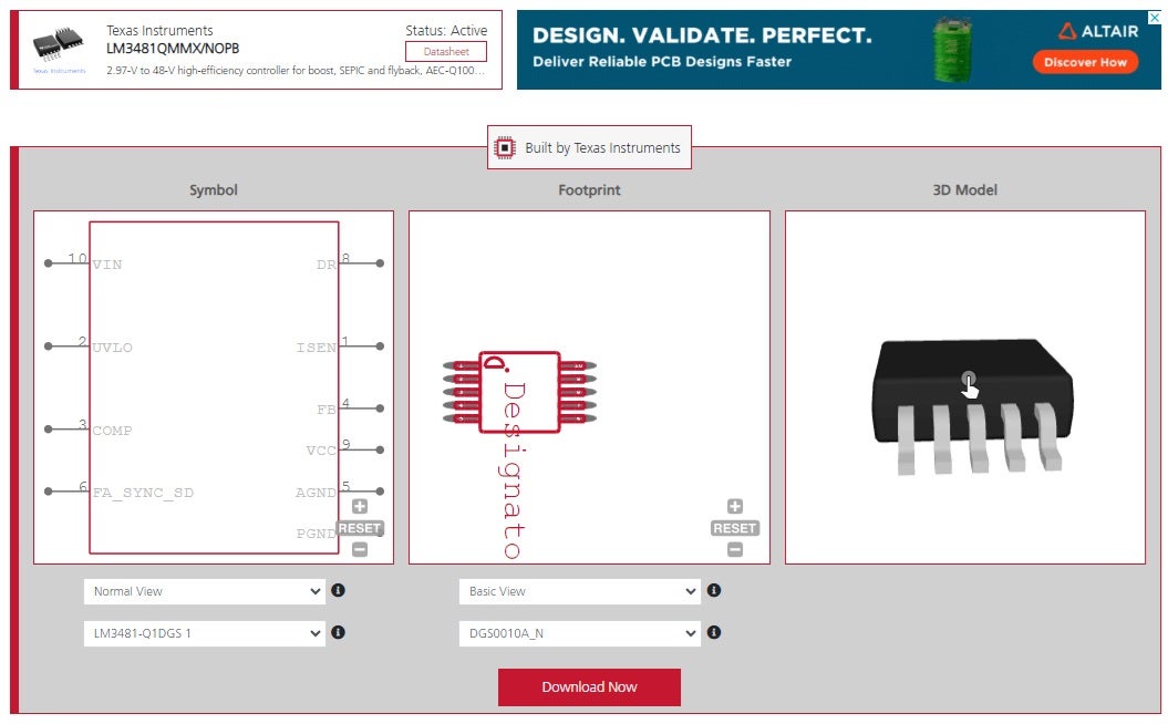
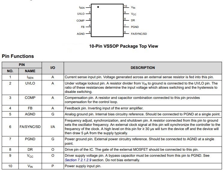
LM3481: Layout and Operation

The component pinout and functional diagram provided in the LM3481 datasheet, is shown below.
LM3481 component pinout and functional diagram

PCB Design and the LM3481 Datasheet

LM3481 datasheet information is helpful, but it is not recommended to create PCB footprints manually. It is relatively easy to make mistakes, which can lead to redesigns, turnaround time delays, and additional costs.
LM3481 schematic symbol, footprint, and 3D CAD model from Ultra Librarian
A more reliable approach is to obtain schematic symbols, footprints, and 3D CAD models from a reputable source, such as Ultra Librarian, and procure the LM3481 from a reputable distributor. If you’re looking for CAD models for common components or important design information like how to best use the LM3481 datasheet for your PCB project, Ultra Librarian helps by compiling all your sourcing and CAD information in one place. Working with Ultra Librarian sets up your team for success to ensure streamlined and error-free design, production, and sourcing. Register today for free.
Exit mobile version