Non-invasive temperature measurements use thermal sensors to read temperature
With very few exceptions, everyone has had to somewhat curtail their movement over the last several months due to the pandemic. These restrictions have been more difficult to bear for some than others. Nevertheless, if you have had the need or desire to enter locations where social distancing is not practical or easily practiced—a school, hospital, or airline, for example—it is likely you have had your temperature taken. Temperature checks may seem like an inconvenience, but just think how much more so it would be if we were still using invasive mercury thermometers.
Today, fortunately, electronic thermometers allow for temperature measurement at the surface or at a distance. These wonderful devices are possible due to the utilization of internal circuit boards mounted with thermal sensors. Typically, thermal sensors are arranged in arrays so precise measurements can be acquired.
Let’s take a look at these components, and the MLX90640 datasheet in particular, which details one of the most commonly implemented thermal sensor arrays. Then we will discuss how to read the MLX90640 datasheet to best aid you during your design process.
Thermal Sensors and Their Applications
As the name implies, a thermal sensor is a device able to measure temperature in a given environment. For many electronics products, the internal temperature of an enclosure or case is of interest. In other cases, the temperature of or over an external area or surface is the region of interest (ROI). The three major states of matter—solids, liquids, and gas (primarily air)—are all used as a source for thermal sensor measurements. There are four common thermal sensor types.
Common Thermal Sensor Types
- Thermocouples utilize the Seebeck Effect, which is the generation of a voltage potential between two dissimilar metals due to temperature differences.
- Thermistors use ceramics or other materials where the resistance changes with a temperature change. This relationship is usually non-linear, therefore, conversion is required to obtain good measurements.
- Resistance thermal detectors (RTDs) operate similarly to thermistors, but are more accurate, as the materials used (often platinum) have well-defined resistance vs. temperature characteristics.
- ICs or semiconductor-based thermal sensors are used for both remote and local measurements. Operation is similar in both cases, which is based upon measuring the temperature of a transistor located nearby or at a distance.
All of the above thermal sensors require near proximity to the source in order to measure temperature accurately. However, the need for non-contact temperature measurements has led to the use of infrared light, which has been used for distant imaging for quite a while. Moreover, some research indicates non-contact IR-based temperature measurements that are typically structured as an array in an electronics package can be just as accurate as the more traditional contact-based methods. There are many applications for these devices, as shown below from the MLX90640 datasheet by Melexis.
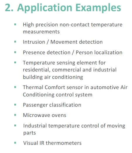
Common applications for the Melexis MLX90640ESF-BAB-000-TU thermal sensor array
Let’s explore this widely used IR-based thermal sensor array in greater detail, especially its distinguishing parameters.
The MLX90640 Thermal Sensor Array
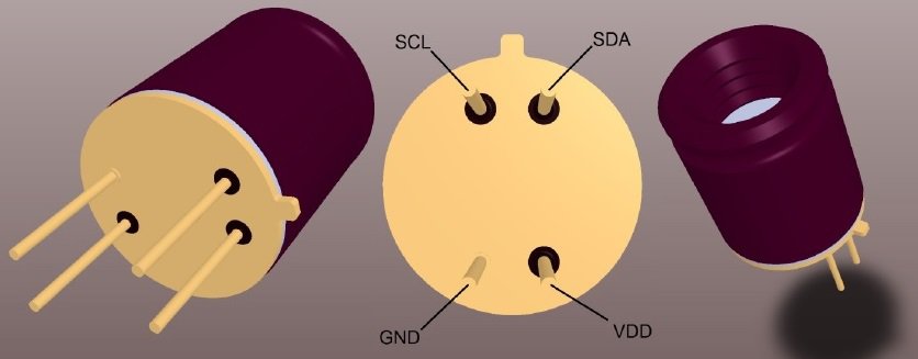
The Melexis MLX90640ESF-BAB-000-TU thermal sensor array
As shown in the figure above, the MLX90640 is a 4-pin through-hole component packaged as a standard TO-39 component. The device is structured as a field array consisting of 32 x 24 (768) IR pixels, includes two field-of-vision (FOV) options: 55° x 35° and 110° x 75°, and is RoHS compliant. Another useful feature of the MLX90640 is its ability to operate as a thermal imaging device, whereby the captured source data is passed along to an image processing stage, bypassing the series of calculations necessary to obtain a temperature measurement, which is summarized in the figure below (from the MLX90640 datasheet).
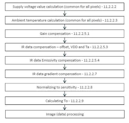
Pixel temperature calculation steps
The series of steps above are required to calculate the temperature for each pixel of interest. The fact that each pixel’s data is stored and can be accessed individually is a major factor for the device’s accuracy. For example, over a non-uniform temperature zone between 0 – 100°C, the maximum deviation should be ±1.5°C. Obviously, the number of pixels, FOV, and accuracy are important considerations when deciding upon a thermal sensing device. The parameters that should inform your choice when choosing the MLX90640 are listed below.
| IMPORTANT THERMAL SENSOR ARRAY PARAMETERS | |
| Parameter | MLX90640 Value |
| Pixel array size | 32 x 24 |
| FOV | 55° x 35° and 110° x 75° |
| Accuracy | ±1.5°C* |
| Supply voltage (Overvoltage) | 3.3V (5.0V) |
| Current consumption | > 23mA |
| Operating temperature | -40°C – 85°C |
| Target temperature range | -40°C – 300°C |
| Communication protocol | I2C |
| Data clock frequency (Max) | 0.4MHz (1MHz) |
| Noise Equivalent Temperature Difference (NETD) | 0.1K RMS @ 1Hz Refresh Rate |
| Package Type | TO-39 |
* For a non-uniform temperature zone between 0 – 100°C.
The above list is not exhaustive, however, the listed parameters are significant, as they define the operating characteristics or ranges that must be adhered to and provide information that is necessary when utilizing the MLX90640 datasheet for your board design.
Using the MLX90640 Datasheet
A good datasheet should provide detailed operational information and parametric data that can be used to compare and contrast components. However, it should also provide the component symbol, footprint, and any preferential connectivity information, as shown in the figure below, to help you design your PCBA layout.
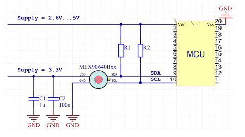
Typical layout connectivity for the MLX90640 thermal sensor array
As shown in the schematic above, the most common configuration for the MLX90640 includes an impedance network (R1 and R2) to isolate the bidirectional data on SDA and clock on SCL from the MCU supply, which may range from 2.6V to 5V. The sensor array itself may be supplied separately at 3.3V or left without a DC source. If the source VDD is used, coupling capacitors should be used as depicted.
When searching for a thermal sensor array to meet your objectives, you need parametric data to help you select the best component, symbols, and footprints to aid in your schematic capture and PCBA layout design. Component specifications, such as an accurate and complete MPN, are necessary to create the bill of materials (BOM) for your contract manufacturer (CM) to build your board with the highest first pass yield. The MLX90640 datasheet meets all these requirements.
If you’re looking for CAD models for common components—such as the MLX90640 thermal sensor array—Ultra Librarian helps by compiling all your sourcing and CAD information in one place, including manufacturer’s datasheets. Working with Ultra Librarian sets up your team for success to ensure any design is going through production and validation with accurate models and footprints to work from. Register today for free.


