Electromagnetic interference (EMI) occurs when sensitive electronic components encounter an electromagnetic field at a frequency that can interfere with the functions of that component. In minor incidents this can look like a lightbulb flickering or some radio static. In worst-case scenarios it could present as a malfunction in advancing technology, like an autonomous vehicle.
EMI noise is becoming more important when considering today’s modern and complex designs, especially in new automotive and industrial applications. Designing for low EMI can save you significant development cycle times while also reducing board area and solution cost.
What Causes EMI Noise?
As devices are becoming more complex, circuits are being packed into closer proximity to one another and therefore are more prone to experience EMI. Sensitive elements are being pushed closer to components that carry large currents and voltages, so all this energy is bound to electromagnetically interfere with these sensitive elements. EMI can present in 2 forms:
- Conducted EMI: a common conduction path affects sensitive electronics.
- Radiated EMI: sensitive electronics are affected through coupling over a medium.
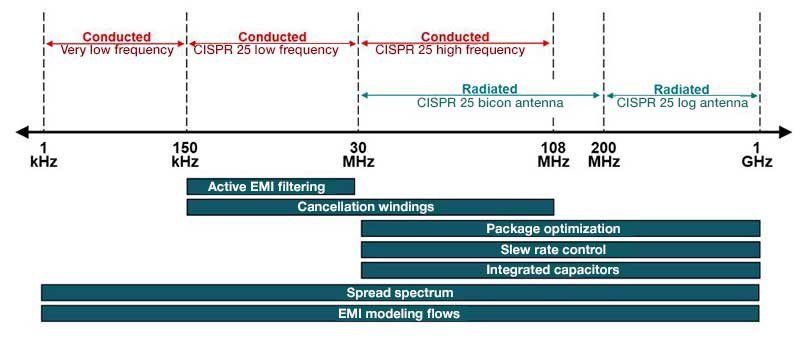
A key source of EMI noise is often the switch mode power supply (SMPS), one of the most common circuits in modern electronics systems. While SMPS is more efficient than linear regulators, the switching of power FETs can be a major source of EMI in this circuit. The switching causes the input currents to be discontinuous, which can impact EMI in the sub 30MHz range. These circuits also have fast edge rates on the switch node with associated ringing that can impact EMI all the way to 1GHz or higher.
How to Mitigate EMI for SMPS
Texas Instruments has been combatting EMI for years through evolutions of their innovative technology. Their advanced spread-spectrum and active EMI suppression technique can reduce the impact of EMI, while their flip-chip packaging, capacitor integration, and advanced gate-driver techniques reduce EMI noise at the source.
There are two main methods to mitigate EMI generated in conventional designs:
- To deal with low-frequency emissions and meet appropriate standards, placing large passive inductor-capacitor filters at the input of the switching converters. However, this leads to a more expensive and less power-dense solution.
- Slowing down the switching edges through the effective design of the gate driver can mitigate high-frequency emissions. While this helps reduce EMI in the >30MHz band, the reduced edge rates lead to increased switching losses and therefore a lower-efficiency solution.
To get the best of all worlds with high power density, increased efficiency, and low EMI, you can utilize several different techniques, shown in the graphic below, that can be found in TI’s switching converters and controllers.

For more information on reducing EMI noise check out TI’s white paper on Time-Saving and Cost Effective-Innovations for EMI Reduction in Power Supplies and their in-depth training series on EMI.


