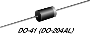
A 1N4004 diode is a general purpose rectifier diode. It is part of the 1N400X series, where ‘x’ varies depending on the specific model. In the case of the 1N4004, it is designed to handle a maximum voltage of 400 volts and a maximum current of 1 ampere.
1N4004 is optimized for rectification, which is the conversion of alternating current (AC) to direct current (DC). When used in a circuit, it allows current to flow freely in the forward direction (anode to cathode) but blocks it in the reverse direction beyond a certain voltage threshold (reverse breakdown voltage). The table below presents the primary characteristics taken from Vishay’s 1N4004 diode datasheet.
|
Primary Characteristics From the 1N4004 Diode Datasheet |
|
|
Characteristic |
Description |
|
Diode type |
General purpose rectifier diode |
|
Maximum repetitive peak reverse voltage |
400 volts |
|
Maximum average forward rectified current |
1.0 amp |
|
Peak forward surge current |
30 amps |
|
Non-repetitive peak forward surge current |
45 amps |
|
Maximum instantaneous forward voltage |
1.1 volts |
|
Maximum DC reverse current |
5.0 μA |
|
Operating junction and storage temperature range |
-50 to +150 °C |
|
Package |
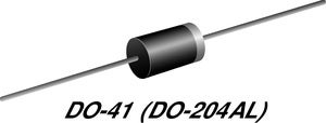
DO-41 (DO-204AL) |
|
Circuit configuration |
Single |
1N4004 Diode Datasheet: Applications
|
1N4004 Diode Applications |
|
|
Rectification of Power Supplies |
In AC to DC power supplies, the 1N4004 diode can be used to convert the AC input into a DC output by allowing current flow only during the positive half-cycles of the AC waveform. |
|
Voltage Clamping |
It can be used for voltage clamping applications, where it limits the voltage level to a specific value. For example, it can protect sensitive electronic components from voltage spikes by shunting excess voltage to ground. |
|
Freewheeling Diode |
When used in circuits with inductive loads such as motors or solenoids, the 1N4004 diode serves as a freewheeling diode. It provides a path for the current to circulate when the inductive load is switched off, preventing voltage spikes that could damage other components. |
|
Reverse Polarity Protection |
Placed in series with a circuit, the diode can prevent damage due to reverse polarity connection by blocking current flow in the reverse direction. |
1N4004: Architecture
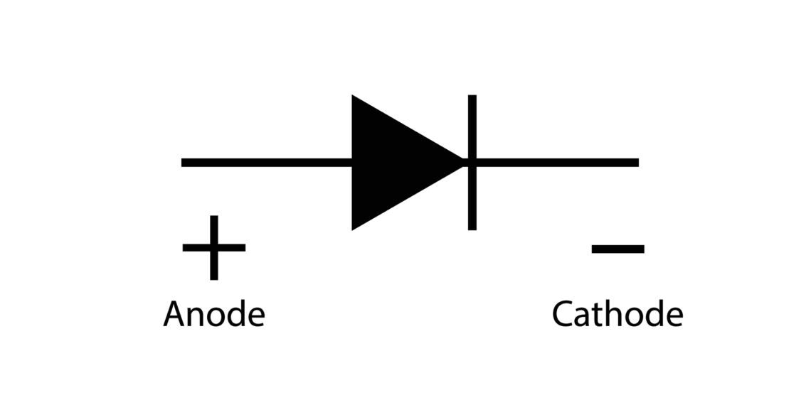
Electronic symbol of basic diode
Here’s an overview of the 1N4004 rectifier diode’s architecture:
- Anode: This is the positive terminal of the diode. Current flows into the diode through this terminal.
- Cathode: This is the negative terminal of the diode. Current flows out of the diode through this terminal.
- P-N Junction: The diode is made of semiconductor material, usually silicon. It consists of a P-type semiconductor and an N-type semiconductor joined together. This junction forms the basis of the diode’s operation.
- Encapsulation: The diode is encapsulated in a package, typically cylindrical or rectangular, to protect it from damage and provide convenient mounting.
1N400X Series Data
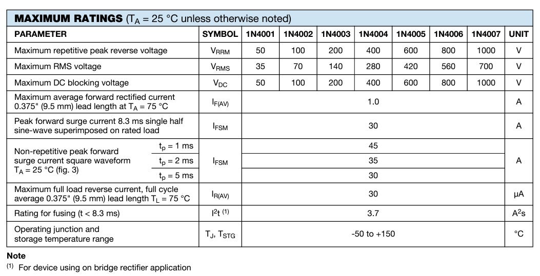
The maximum ratings of a diode are crucial for PCB designers, as they define the operational limits within which the diode can function reliably without risk of damage or failure. By understanding these ratings, designers can ensure that the diodes in their circuitry are not subjected to conditions that could cause harm, maintaining reliability, safety, and compliance with industry standards. Adhering to maximum ratings also enables designers to optimize circuit performance and efficiency while mitigating the risk of component failure, ultimately ensuring the integrity and longevity of the electronic systems they develop.
Here are the maximum ratings for the 1N400X series (1N4001-1N4007) of diodes as presented in the datasheet:
The electrical and thermal characteristics of diodes are also important to know because they enable PCB designers to accurately select and integrate diodes into their circuits while ensuring optimal performance and reliability. Here are those characteristics from the datasheet.
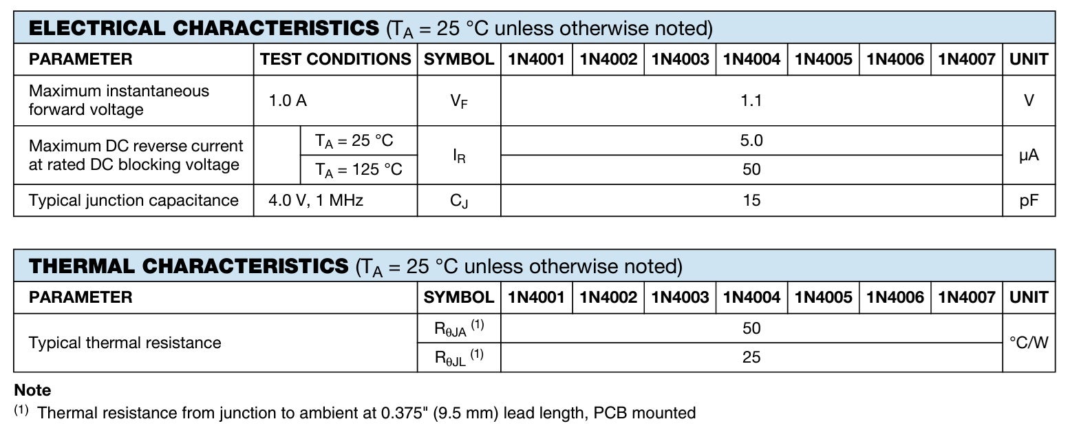 By considering both electrical and thermal properties, designers can design PCB layouts and incorporate heat management strategies that maximize the efficiency, reliability, and lifespan of the electronic systems they develop.
1N4004 PCBA Design Essentials
As shown in the schematic, footprint, and 3D model below, your component’s CAD model and data must be accurate and from a trusted database to be helpful.
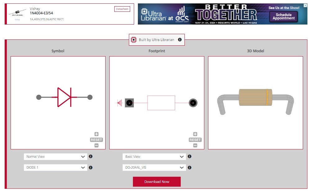
1N4004 schematic symbol, footprint, and 3D CAD model from UL
Online databases are indispensable for finding and comparing parts and avoiding supply chain issues like obsolete part models or data. You can design your PCB effectively and efficiently by combining manufacturer-vetted PCB layout data with the specific specifications, characteristics, and performance metrics of the components found in their datasheets.
UltraLibrarian provides all your sourcing and CAD information in one place, whether you’re looking for CAD models for common components or how to use the 1N4004 diode datasheet.
Working with Ultra Librarian sets up your team for success to ensure streamlined and error-free design, production, and sourcing. Register today for free.


