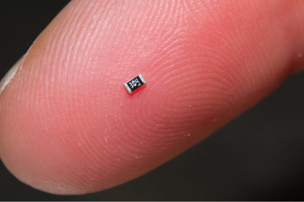
For many through-hole components, there is a surface-mount equivalent available for your PCB. Thanks to standardization in the electronics industry, designers have multiple options for common components that come in a standard footprint. This makes it easy to source large orders of comparable components from multiple manufacturers and quickly replace a component, should it become unavailable.
This is particularly true for SMD components, which have common package sizes and land patterns. Replacing an out-of-stock or obsolete SMD component is a simple matter of using your ECAD software. For SMD passives (resistors, inductors, and capacitors), 0603 package footprints are among the most popular, thanks to their very small land area, low price, ease of assembly, and large range of compatible components from multiple manufacturers. Here’s how to identify and import 0603 package footprints in your ECAD software and some important specifications on these packages.
What Is in 0603 Package Footprints?
SMD package footprints have two different naming and sizing standards that specify footprints for 0603 components in metric and imperial units. When someone refers to an “0603 SMD component,” they are almost universally referring to the imperial version of the 0603 package footprint. The 0603 metric package has the same dimensions as an 0201 imperial package.
The package name is correlated with its land pattern in inches. So the “06” in the 0603 package name means it is .06 inches in length and the “03” means it is .03 inches in width. The standard dimensions of an 0603 package are:
- Length: 1.55 ± 0.05 mm
- Width: 0.85 ± 0.05 mm
- Height: 0.45 ± 0.05 mm
Because of this potential for confusion, component manufacturers overwhelmingly default to using the imperial code designation, as specified in the Electronics Industries Alliance (EIA) standard, when referring to component packages. However, if you look at component datasheets, units for imperial package codes are often specified in mm, not in mils or inches. Here is a full table of imperial and metric size codes, as well as standard package sizes.
Dimensions
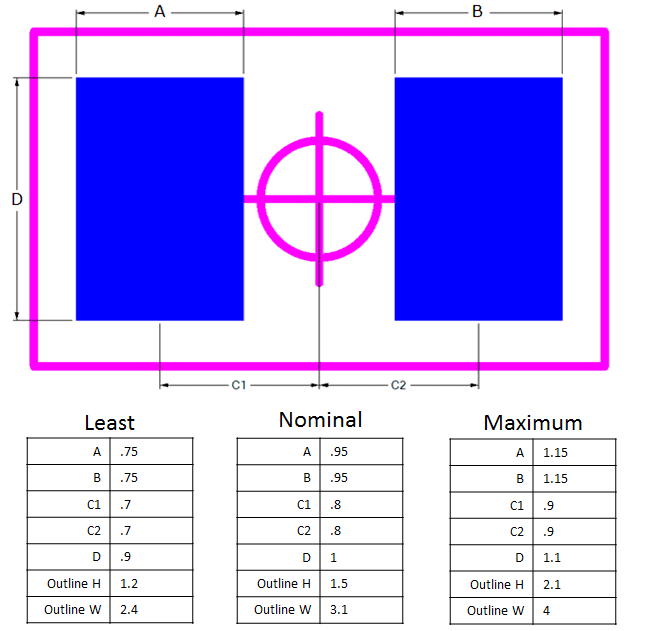
Because the IPC 7351 standard provides some leeway on pad sizes and land patterns, not all 0603 package footprints have the same dimensions. It is a good idea for designers to confirm the dimensions of their desired 0603’s datasheet to see if it meets the typical sizing. Designers who assume all 0603s are the same might encounter errors later in their process.
In general, the land pad arrangement covers the electrical contact beneath the package and extends beyond the edge of the electrical contacts. This gives some room for soldering during assembly and allows for minor shifts in the component without creating an open circuit. The smallest, nominal, and largest 0603 pad sizes and spacing are shown in the image below. Note that the image depicts the standard 0603 imperial package, but the units below are shown in mm.

Some land patterns have rounded corners, although the lateral pad dimensions and center-to-center spacing will be the same. No matter what 0603 package footprint you use in your device, they will be interchangeable between different components. If a desired component is unavailable and you need to swap for a replacement, you can create the new component with the same PCB footprint and 3D model as long as the packages match.
Land Pattern Standards
The IPC standard pertaining to SMT footprints is IPC-7351, Generic Requirements for Surface Mount Design and Land Pattern Standard. Many CAD tools include a calculator or a footprint generator that will create compliant land patterns for PCB footprints. If you want to calculate SMD land patterns by hand, pay attention to the dimension tolerances shown above.
Typical 0603 Electrical Ratings
The typical electrical ratings for passives are often cited as specific values, but there is no standard set of electrical ratings for 0603 packages. Resistors, inductors, and capacitors also have different relevant specifications to consider. These values will heavily depend on the materials used to build the component. Some typical values you’ll see for resistors, inductors, and capacitors are shown in the tables below.
0603 Resistor Ratings
| Parameter | Value |
| Resistance | Any value up to MOhms |
| Maximum power | Typically 1/10 or 1/16 W, but some models reach 2.5 W |
| Tolerance | As low as 0.01% |
0603 Capacitor Ratings
| Parameter | Value |
| Capacitance | Generally low (~nF), some high ESR components can have uF values |
| Maximum voltage | Up to hundreds of V, but the capacitance may be low (less than 1 nF) |
| Materials | Same materials as those used in radial and axial capacitors |
0603 Inductor Ratings
| Parameter | Value |
| Inductance | Generally low (up to hundreds of ~nH) |
| Maximum current | ~1-2 A maximum |
| Saturation current | ~1-2 A maximum |
| Tolerance | As low as 1% |
In general, 0603 inductors will have a lower inductance value than larger packages. The same is true for capacitors. These limitations are simply because these values depend so heavily on the package size. 0603 capacitors will tend to have low voltage ratings because the electric field between the two ends of the capacitor will be very high when the package is small. For resistors and inductors, the power/current ratings tend to be low because these factors create heat in the package, and less heat is required to heat a small package up to its maximum temperature.
Under these limitations, if you are designing a high voltage/high current/high power system and need to select passives, you will need to use physically larger components. For high-frequency RF systems, there are specialty 0603 RF capacitors and inductors with weak parasitic values in the package, so their impedance will be reliable up to very high frequencies. Once you’ve determined the type of components you need, you can find 0603 package footprints quickly by using an E-parts finder.
When you are looking for 0603 package footprints and 3D models in vendor-specific and vendor-neutral file formats, you can find the components you need with the parts search features in Ultra Librarian. You will have access to verified CAD models directly from manufacturers, which can be imported into popular ECAD applications. You will also have access to sourcing information from worldwide distributors.
Working with Ultra Librarian sets up your team for success to ensure any design is going through production and validation with accurate models and footprints to work from. Register today for free.


