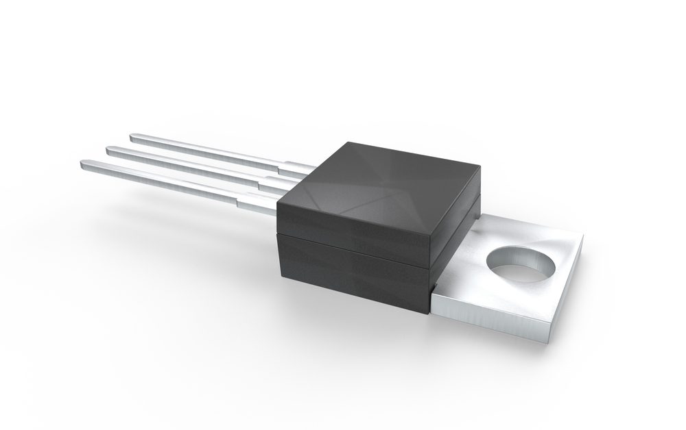
The IRLZ44N is commonly available in a TO220 package.
High power devices need to be safe, operate within appropriate temperature limits, and provide high power conversion efficiency. Some power systems may also need to be actively controlled via user input or a feedback loop, allowing power regulation and conversion to be adjusted. With so many MOS transistors marketed as power MOSFETs, how can designers choose the best option for their power system?
One great option for power systems that require logic-level control while still accepting and withstanding high power is the IRLZ44N power MOSFET from Infineon. This component is also popular for power systems that may not need logic level control but still need to accept a high voltage input to drive the MOSFET deep into the ON state.
When you want to use this component in your design, take a look at the IRLZ44N datasheet before adding the component to your PCB layout.
Power Systems Design with IRLZ44N Power MOSFETs
The IRLZ44N is an N-channel enhancement-mode (normally on) MOSFET that can be used in power systems to support high current output in many topologies. Originally produced by International Rectifier in a TO-262 package under MPN IRLZ44NL, this component is now sold by Infineon as a Pb-free component under MPN IRLZ44NPBF in a TO-220 package, while the original IRLZ44N component is listed as obsolete. While this component does not have the highest drain current or drain-source voltage rating, it does compete well with other MOSFETs produced by Infineon and other manufacturers.
Specifications in the IRLZ44N Datasheet
The IRLZ44N is commonly used in a standard TO-220 package, and a variant with MPN IRLZ44NSTRLPBF is available in a D2PAK package. Both components provide the same specifications, including rated operating temperature and electrical specifications. The important specifications found in the IRLZ44N datasheet are shown below.
| Specification | Value |
| Maximum drain current | 41 A continuous DC, 160 A pulsed |
| Breakdown drain-source voltage (VDS) | 55 V |
| Threshold gate-source voltage (VGS) | 1 to 2 V |
| Base-emitter saturation voltage | Approximately -1.1 V |
| Terminal capacitance (VGS = 0 V, VDS = 25 V) |
|
| On-state resistance |
|
| Transition time | ~100 ns |
| Operating temperature | -55 °C to 175 °C |
Application Areas
The main advantage of the IRLZ44N over other components is its operating temperature for its given drain voltage rating. The high-temperature rating of 175 °C makes this component an excellent choice for power systems drawing high current or systems to be deployed in harsh environments such as industrial settings, aircrafts, or vehicles. One should note, however, that this component does not have any SAE, UL, MIL-SPEC, or other industry-standard ratings, and it is advisable to use an alternative component for power systems in these applications.
Although the IRLZ44N has not received specific qualifications by industry groups or standards organizations, it can still be used in many power system topologies. Common applications include the following topologies:
- High voltage linear regulators
- Non-resonant switching converters (buck/boost/buck-boost topologies)
- Resonant switching converters (half-bridge or full-bridge topologies)
In these topologies, the IRLZ44N can be used as a high-side switch (non-resonant topologies) or as a gate driver (e.g., an LLC resonant converter) as long as the drain current and VDS breakdown ratings are not exceeded.
Logic Level Triggering IRLZ44N in Power Systems
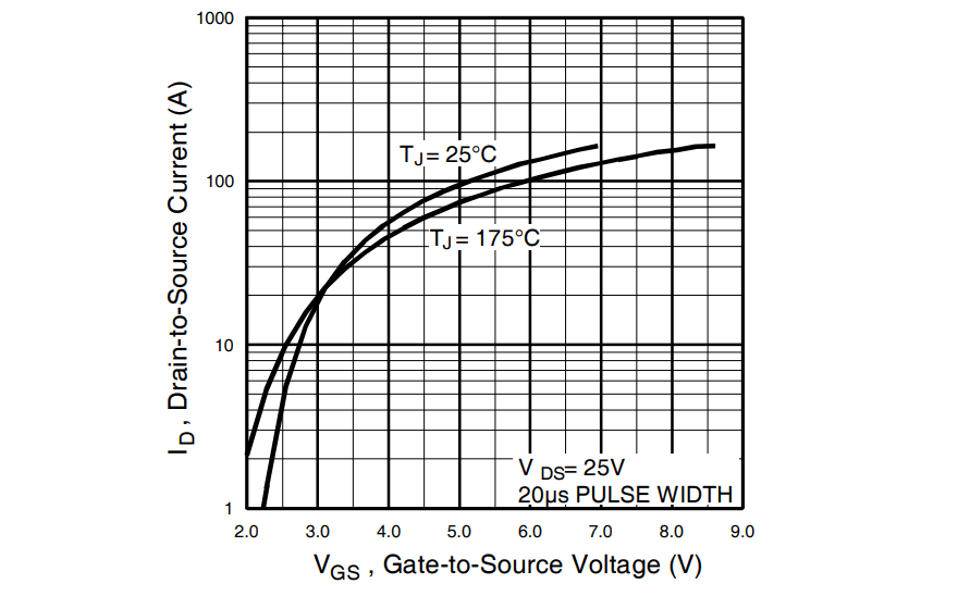
In addition to the temperature rating and high electrical ratings for VDS and drain current, the major advantage of the IRLZ44N is its low gate voltage threshold. The gate threshold is low enough that an IRLZ44N can be driven reasonably far into the ON state with a GPIO pin on an MCU. Anything from 5 V logic families to LVCMOS logic can output sufficient voltage to drive the IRLZ44N with relatively low on-state resistance, as can be seen from the transfer characteristics (see the graph below for a summary).

Drain current vs. VGS, taken from the IRLZ44N datasheet.
Using PWM Driving
For switching converters, the IRLZ44N would need to be switched with a PWM driver (for lower power systems). This can be controlled with a high voltage comparator or current sense amplifier and an MCU, which would allow the PWM duty cycle to be adjusted to ensure stable output voltage. For something like an LLC resonant converter, a more specialized LLC controller should be used, as the PWM driving frequency needs to be adjusted to ensure the LC stage acquires sufficient gain to maintain the desired output voltage and current. In any case, the peak voltage can be rather low and fast edge rates are not required to fully drive an IRLZ44N.
Getting to Higher Current
When higher currents are needed, multiple IRLZ44N transistors can be arranged in parallel, although be careful with this arrangement. When this arrangement is driven between OFF and ON states, a strong oscillation can result due to parasitic capacitance and inductance in the terminals and the circuit arrangement. This is normally solved by placing a small resistor (~10 Ohms) in series with the gate terminal, which will enforce damping on the transient response. You won’t find this type of information in an IRLZ44N datasheet, so be mindful of these types of power integrity problems when designing power systems.
There are other alternative MOSFETs from Infineon that provide logic-level driving with high voltage and current ratings. Whether you need an IRLZ44N datasheet, alternative MOSFETs with different ratings, or other components to support a power system, you can find component models for your parts with the electronics search engine features in Ultra Librarian. You’ll have access to verified CAD models that can be imported into popular ECAD applications and you can view sourcing information from worldwide distributors.
Working with Ultra Librarian sets up your team for success to ensure any design is going through production and validation with accurate models and footprints to work from. Register today for free.


